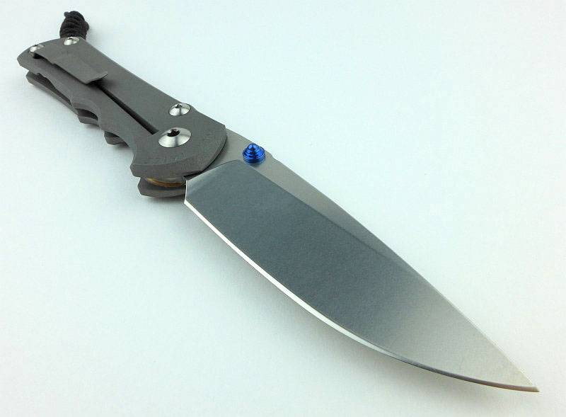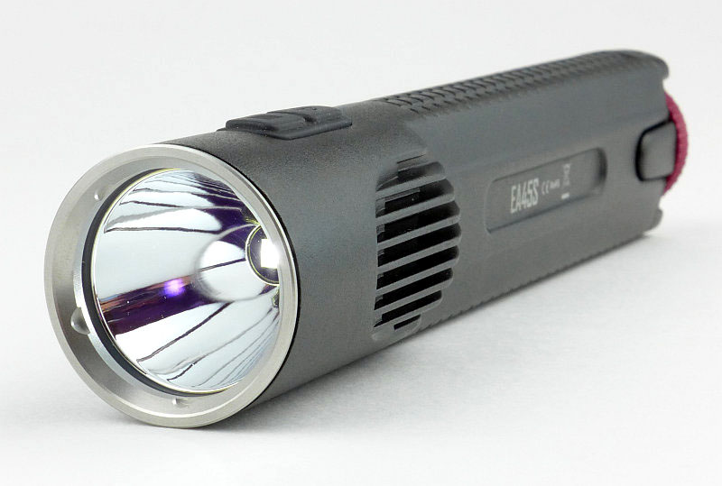
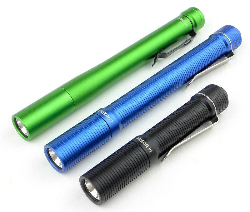
FOURSEVENS’ Preons have been very popular and well regarded AAA powered EDC lights. Being time for a reboot, here are the current updated versions of the Preon P1 and P2.
(And yes, they do have a high efficiency XP-L LED.)
Taking a more detailed look:
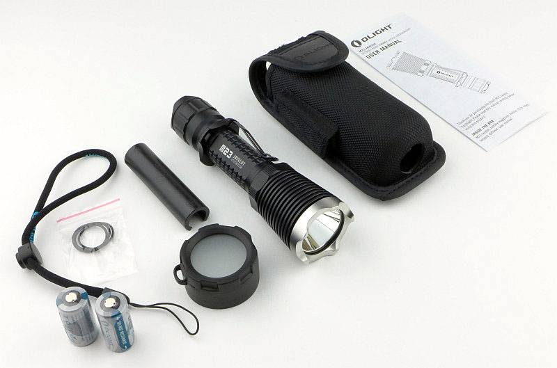
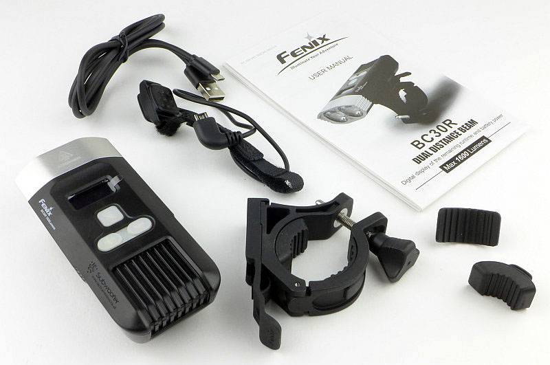
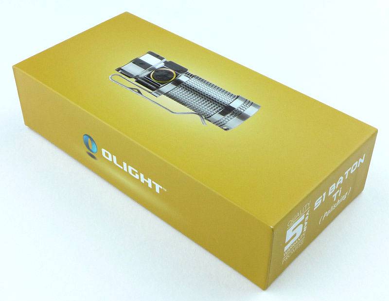
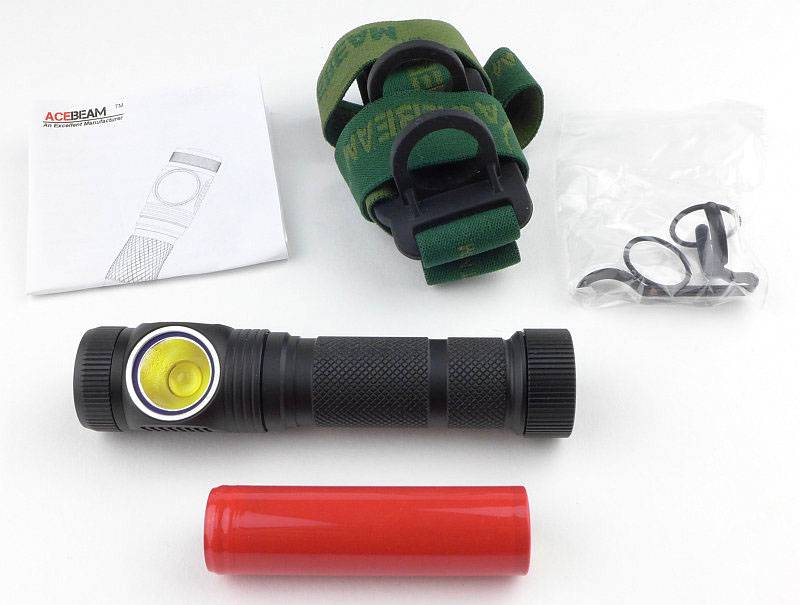
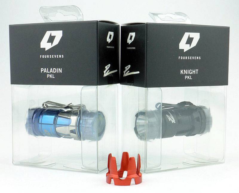
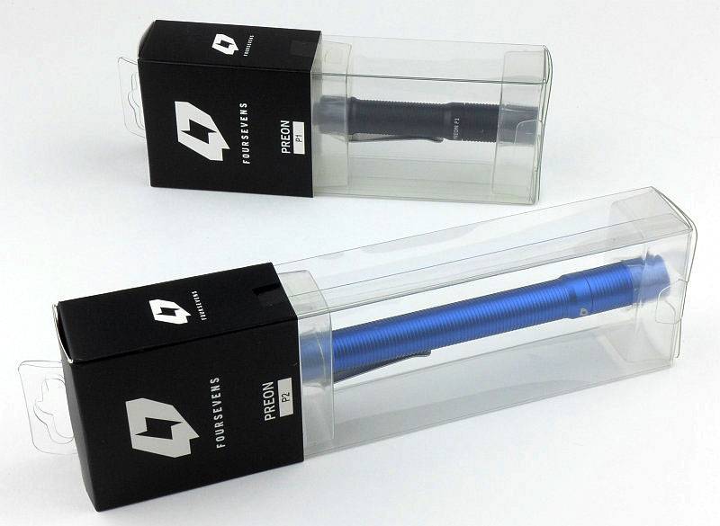
Presentation is great with FOURSEVENS’ standard clear plastic box packaging.
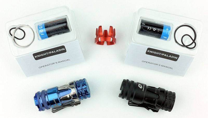
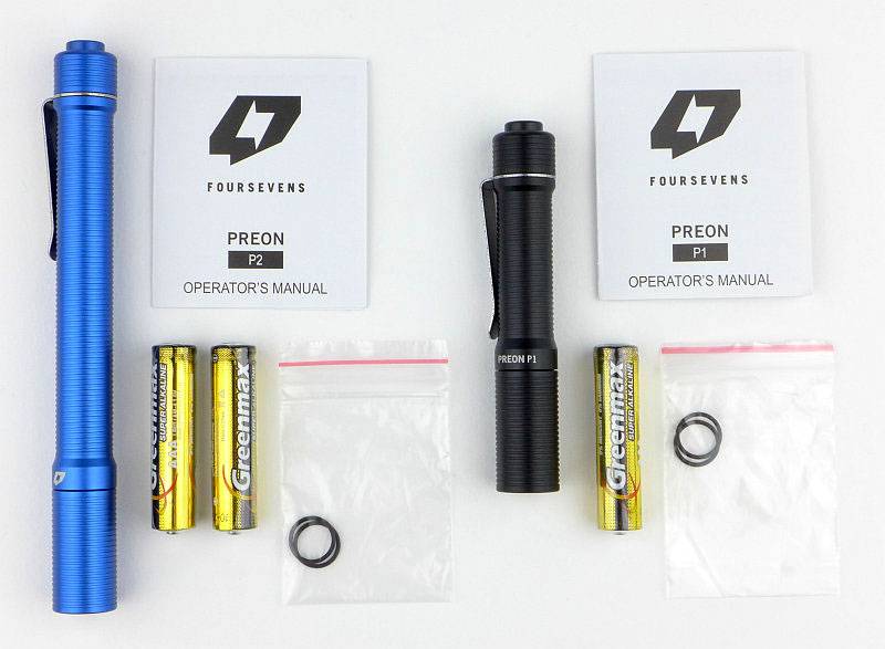
Each Preon comes with one set of AAA Alkaline cells, two spare O-rings and the instructions.
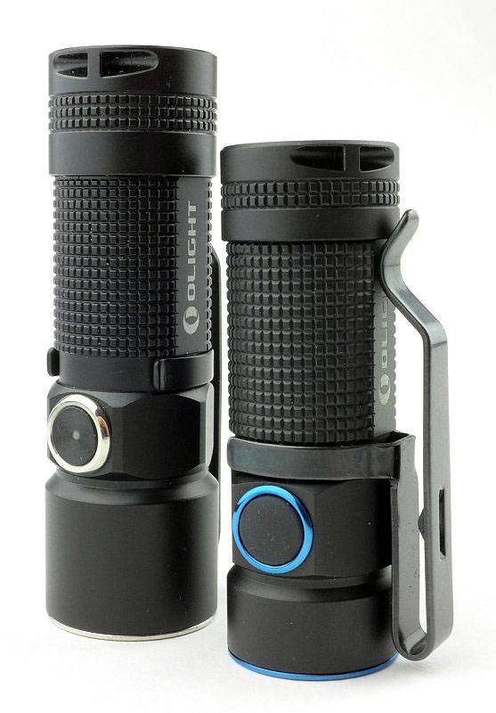
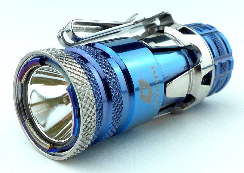
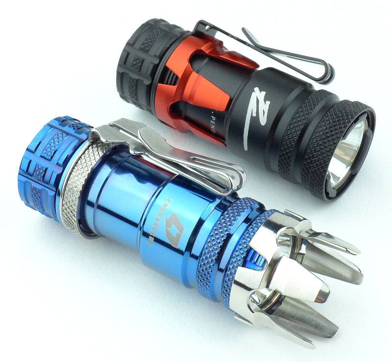
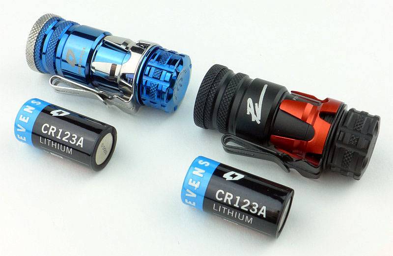
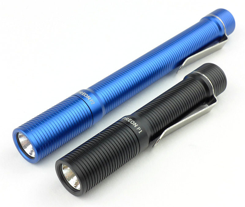
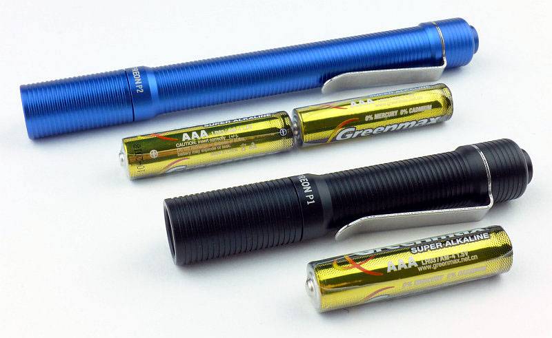
A quick look at the previous generation Preon P2 (in toxic green) with the latest generation Preon P1 and P2.
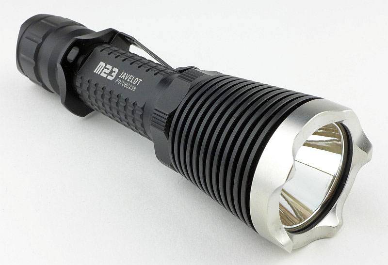
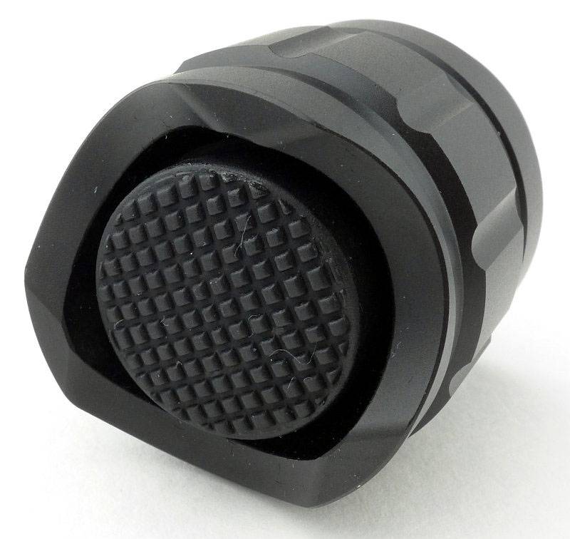
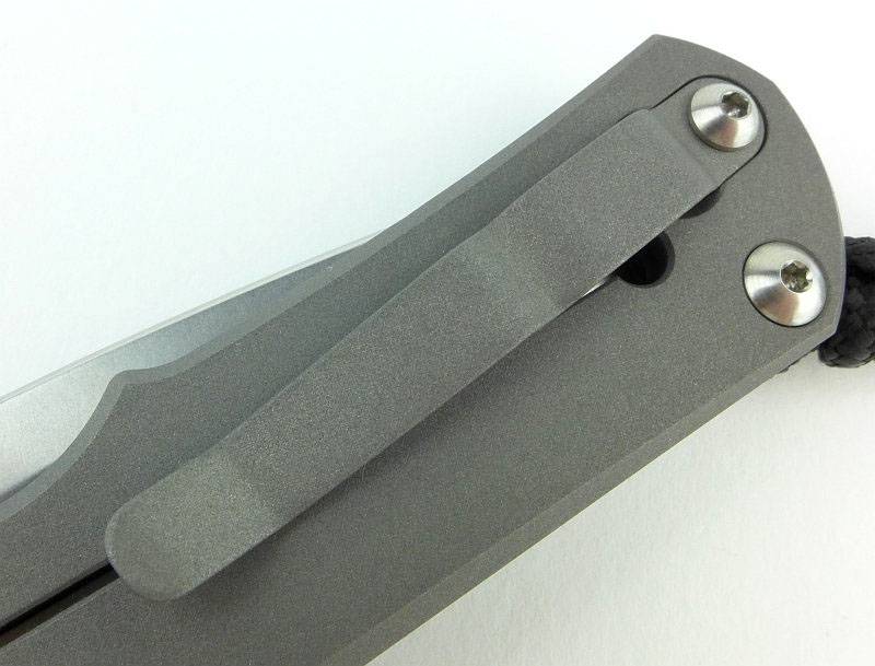
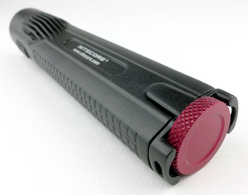
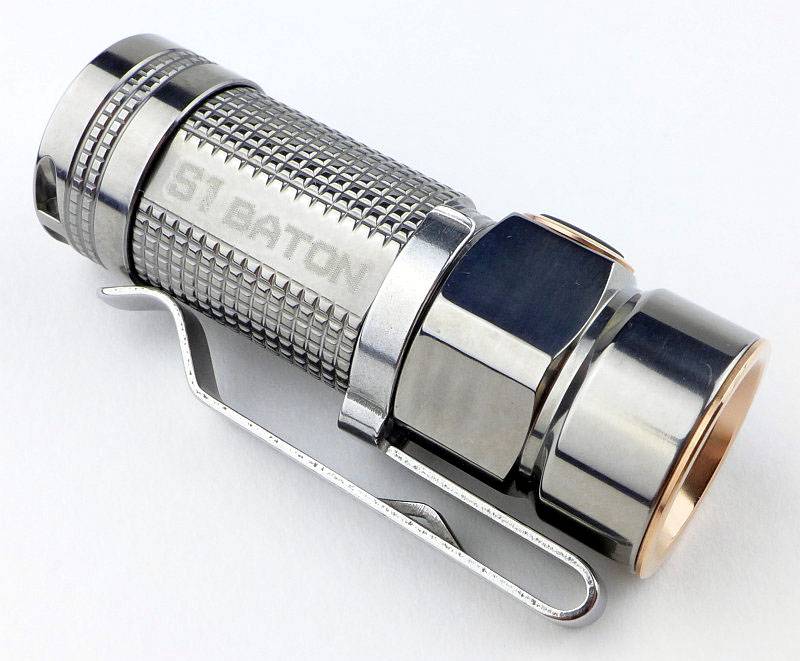
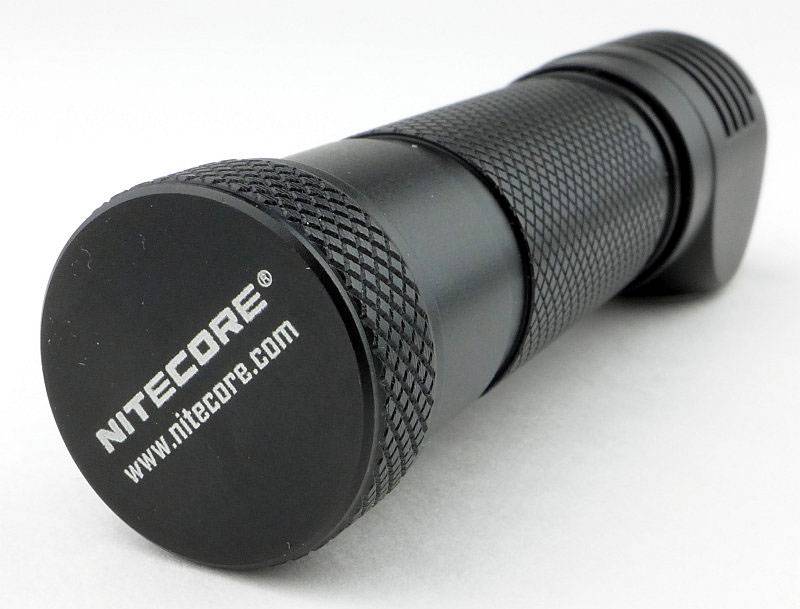
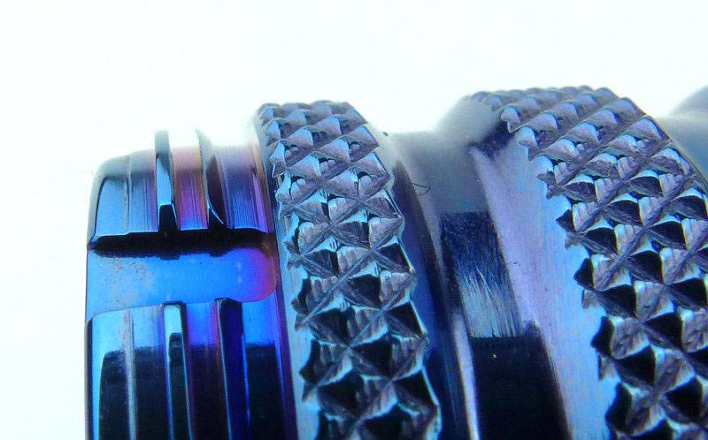
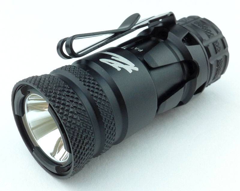
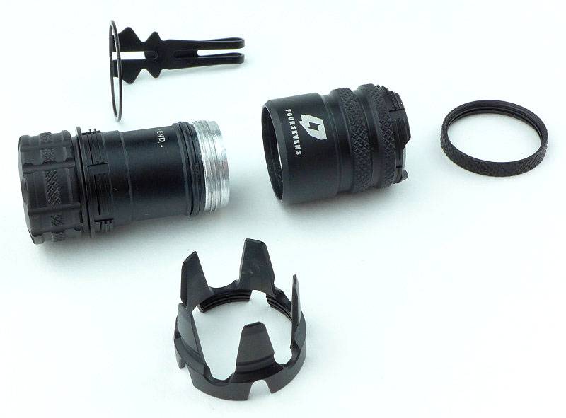
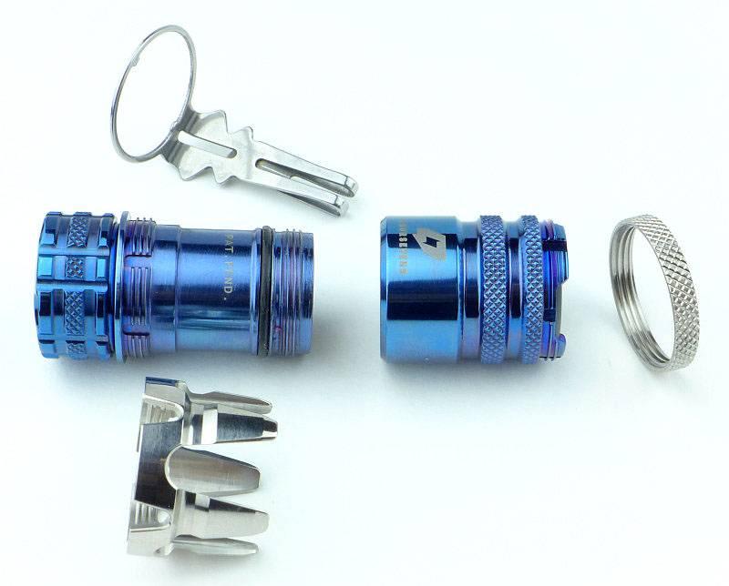
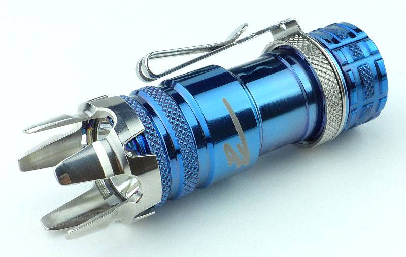
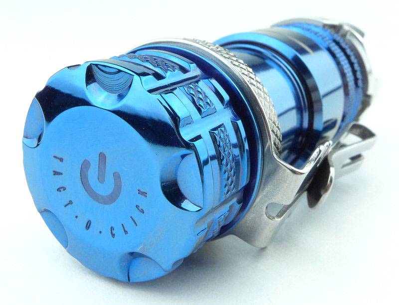
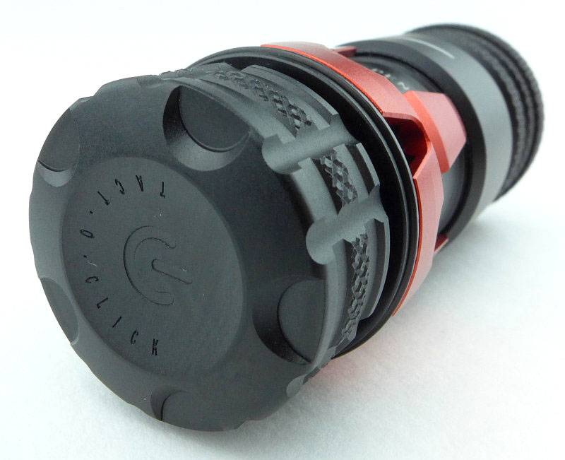
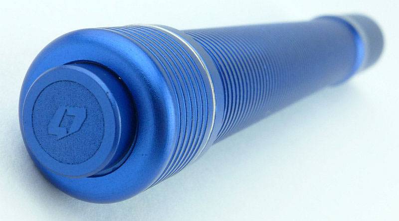
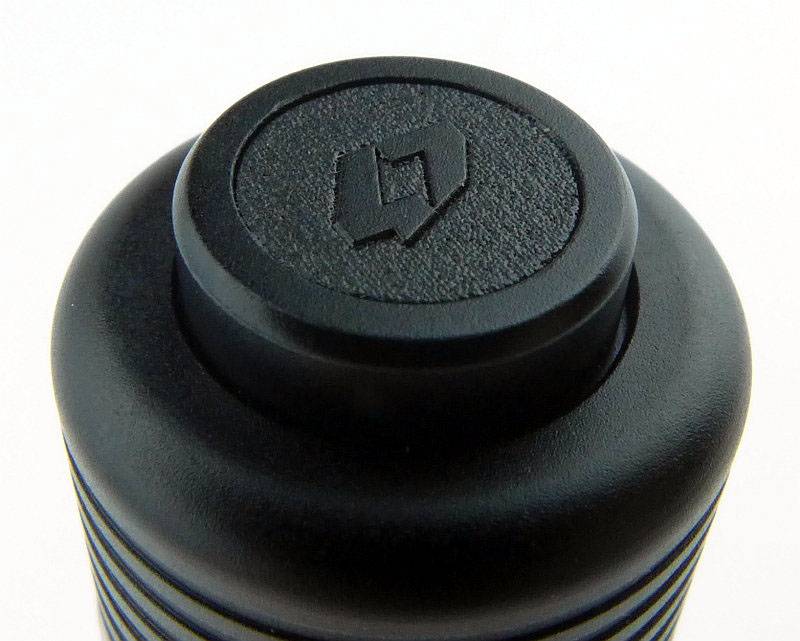
A feature of the Preons is the metal switch button. Prior to anodising, this has been engraved with the FOURSEVENS logo.
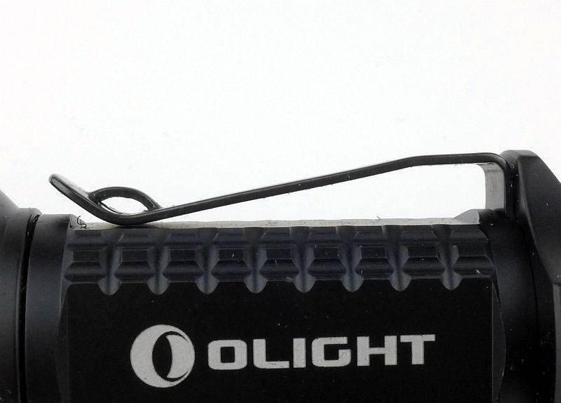
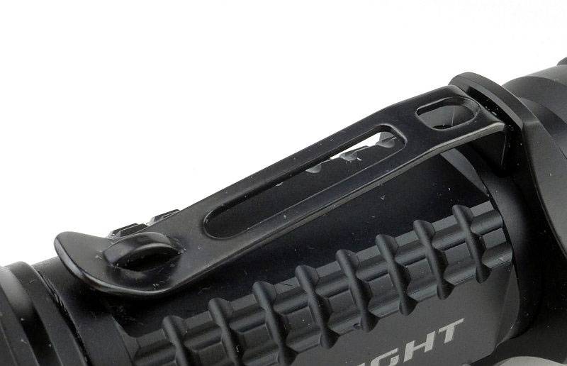
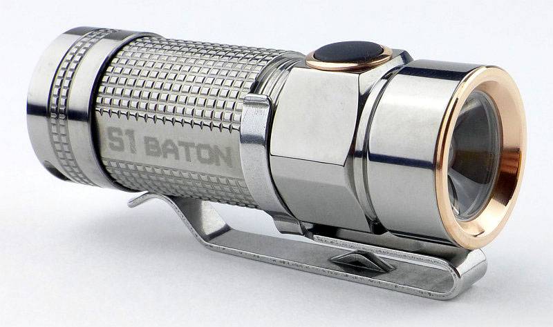
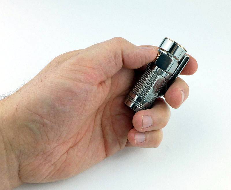
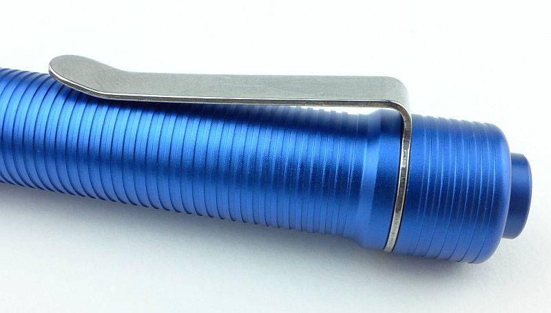
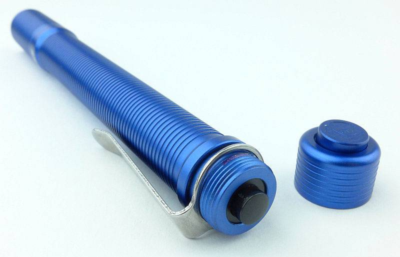
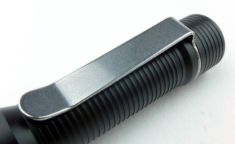
The stainless steel pocket clip is a well finished and has a well-suited tension (not too stiff) to the size and weight.
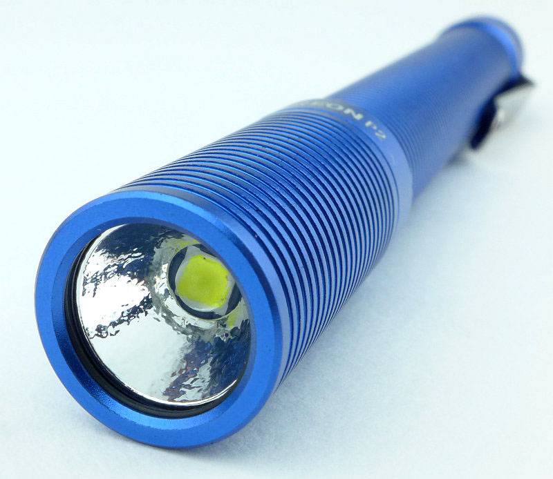
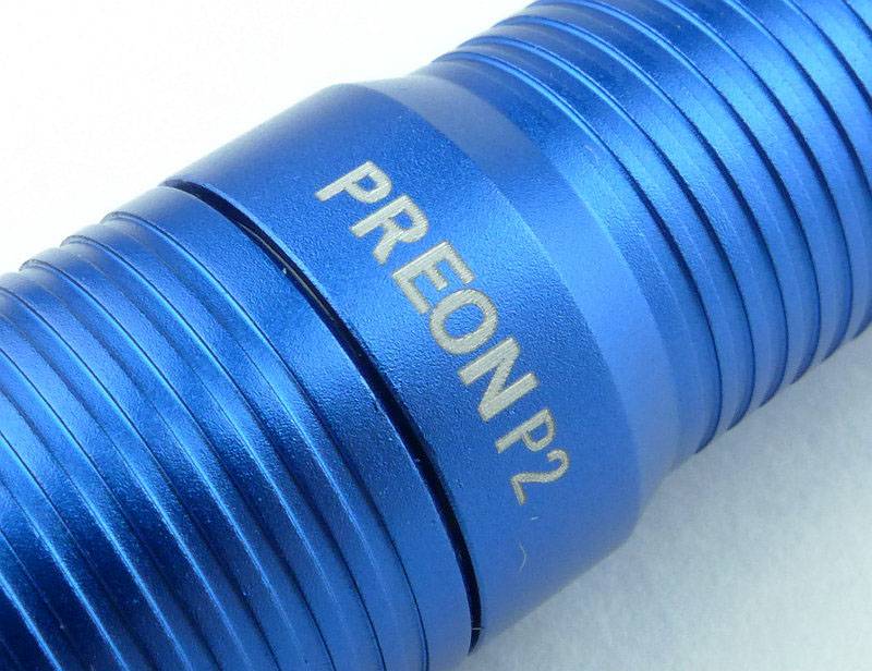
Just above the head of the light the FOURSEVENS logo is laser engraved through the anodising.
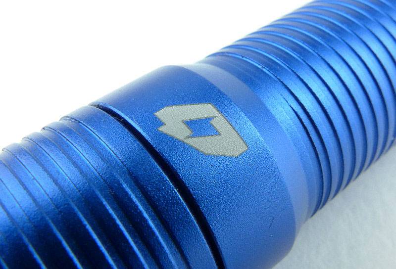
On the opposite side the model is engraved.
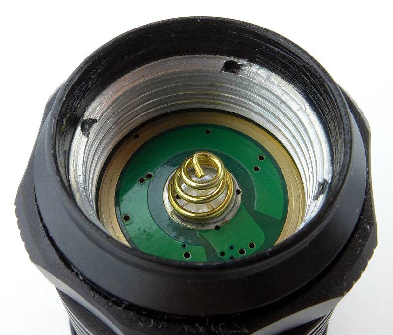
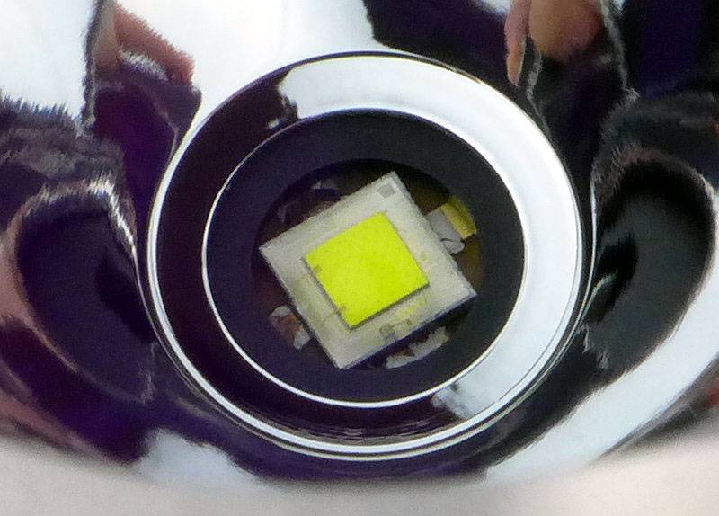
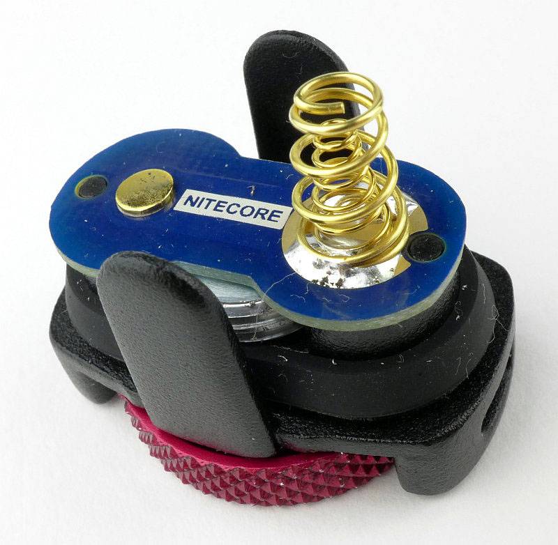
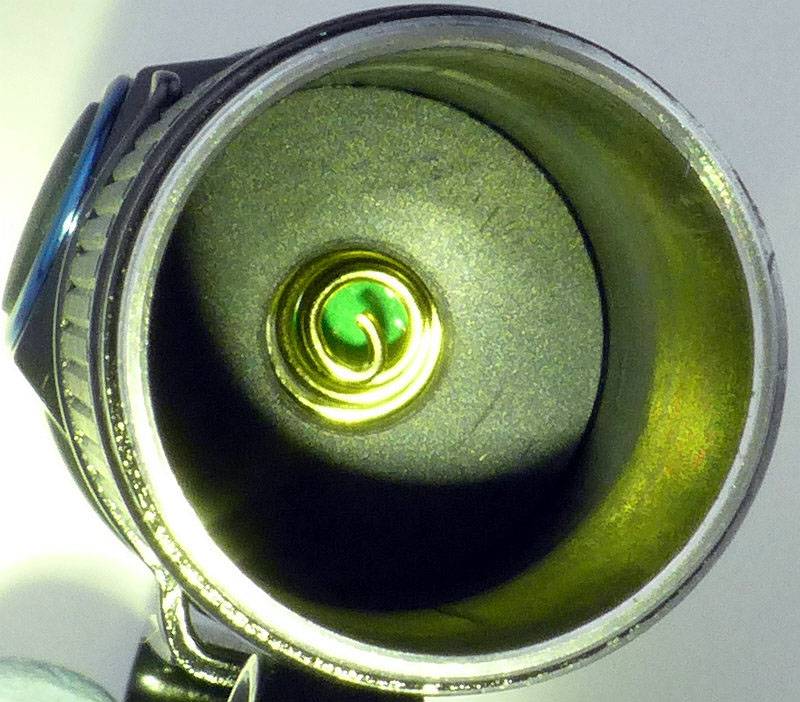
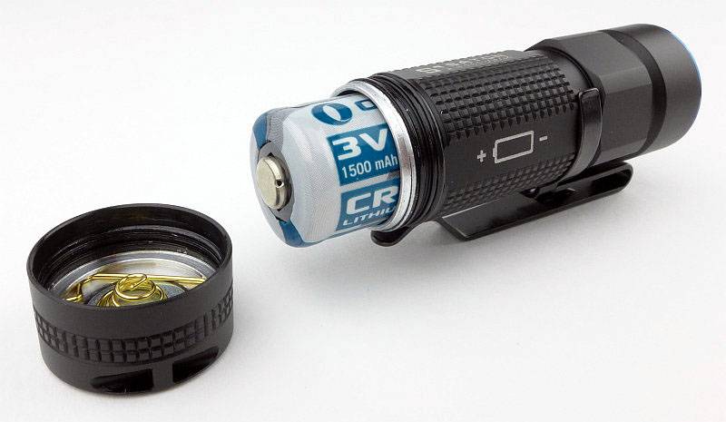
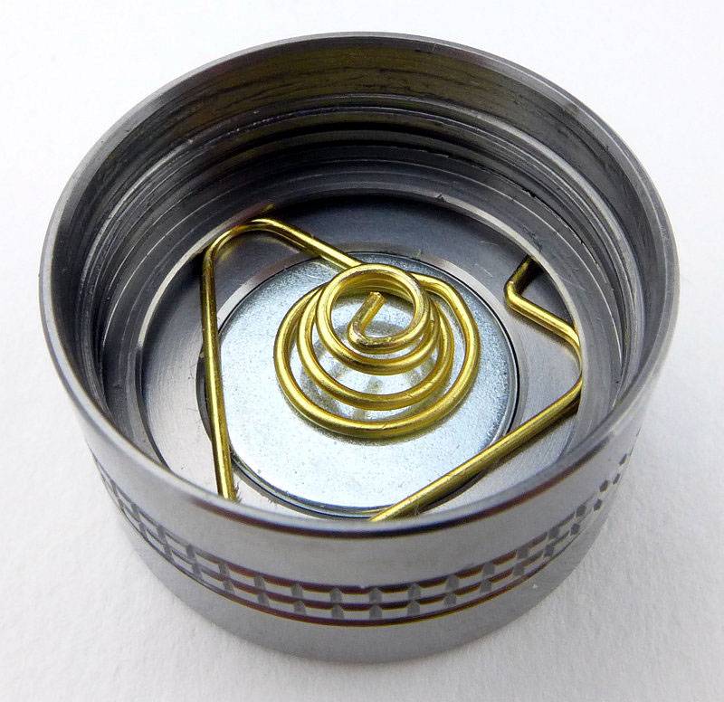
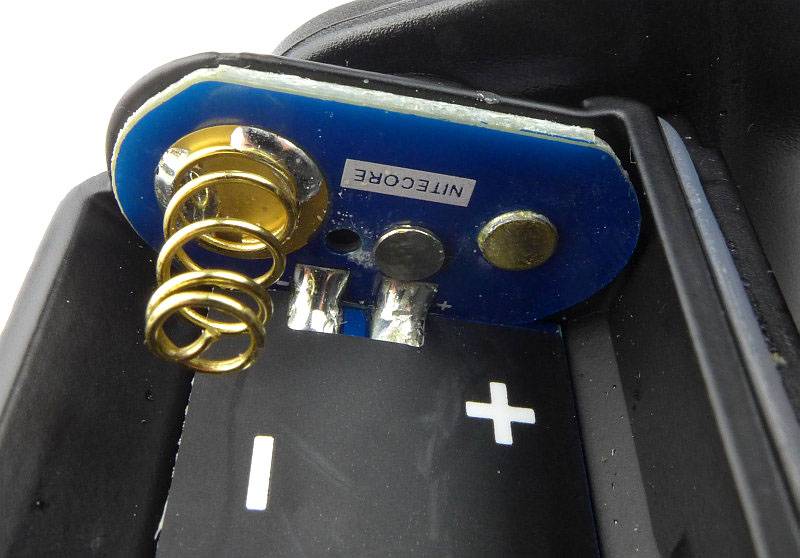
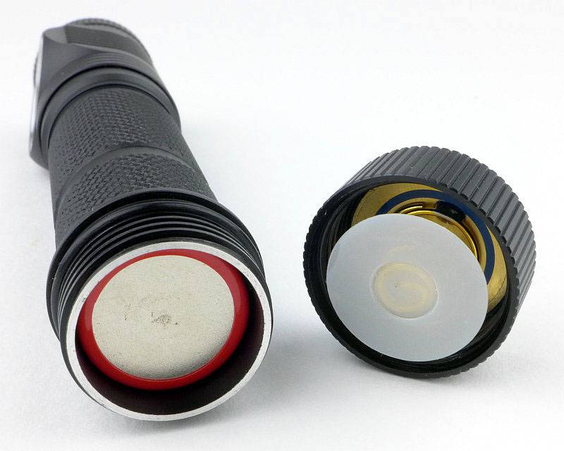
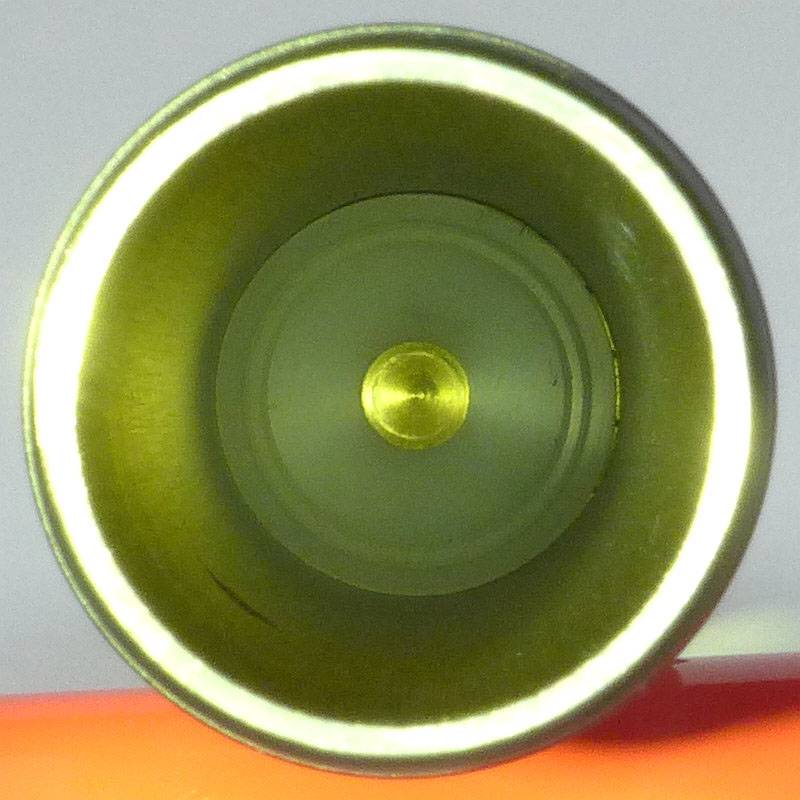
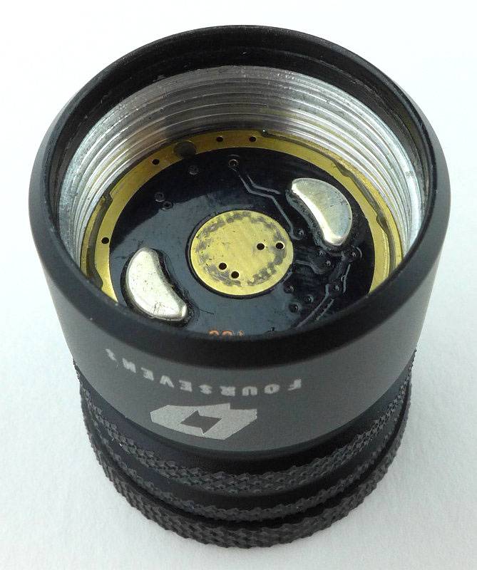
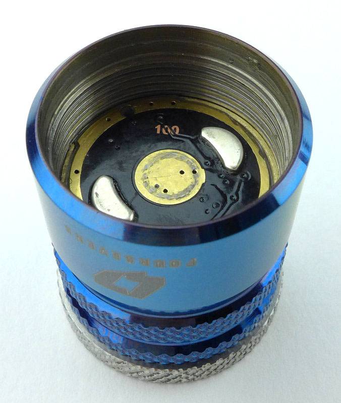
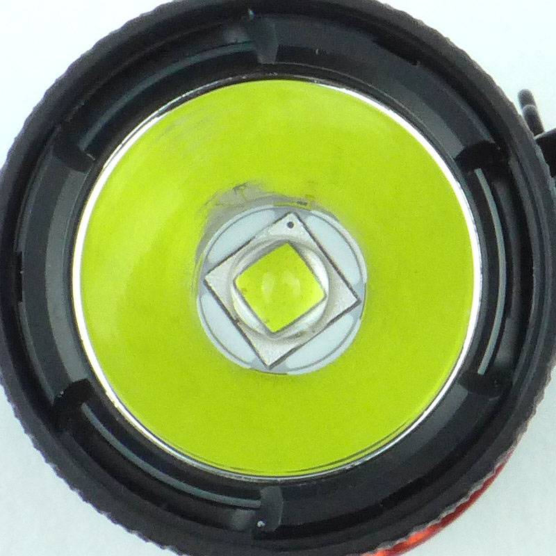
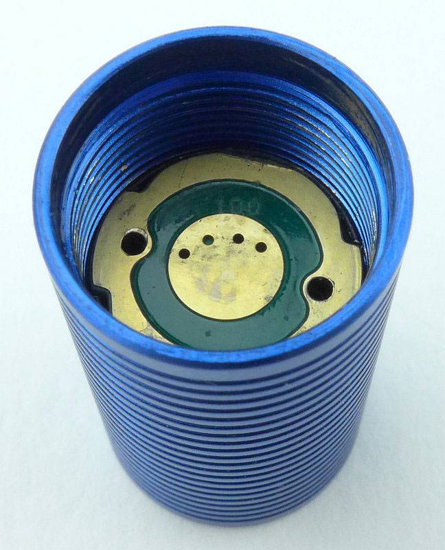
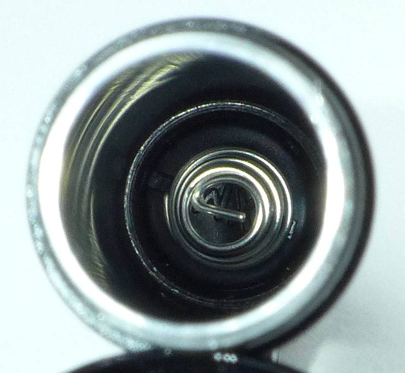
A view of the contacts inside the head. (This is the same for the P1 so the P1 is not being shown.)
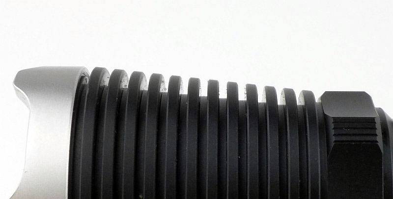
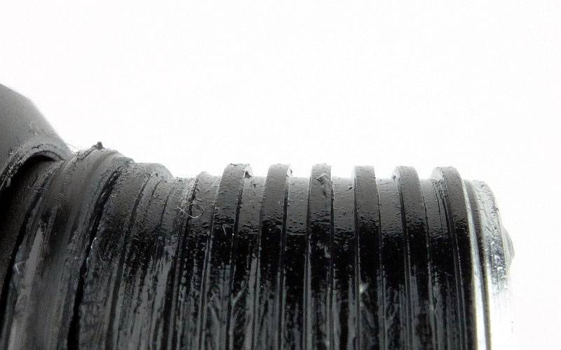
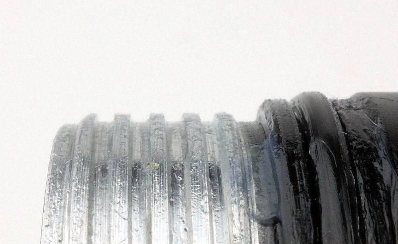
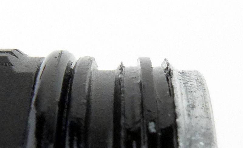
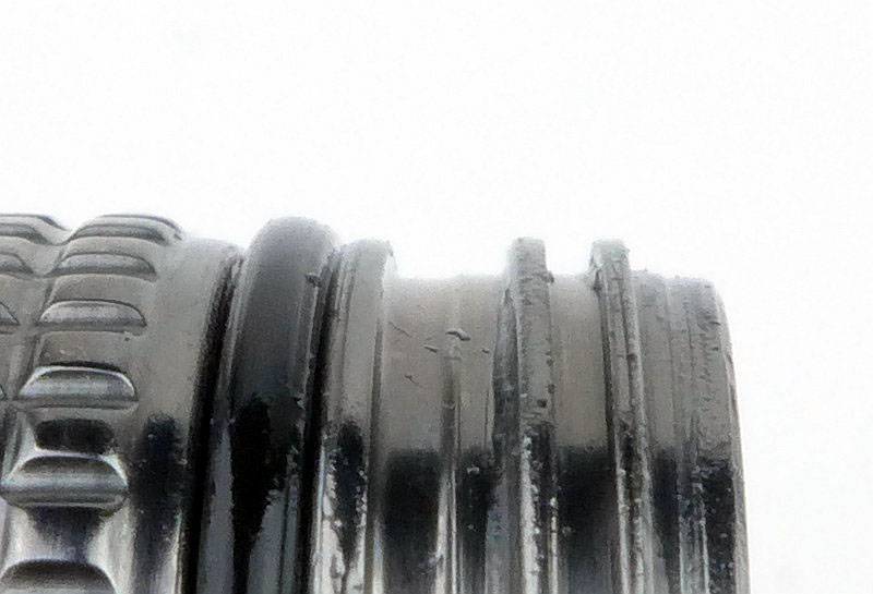
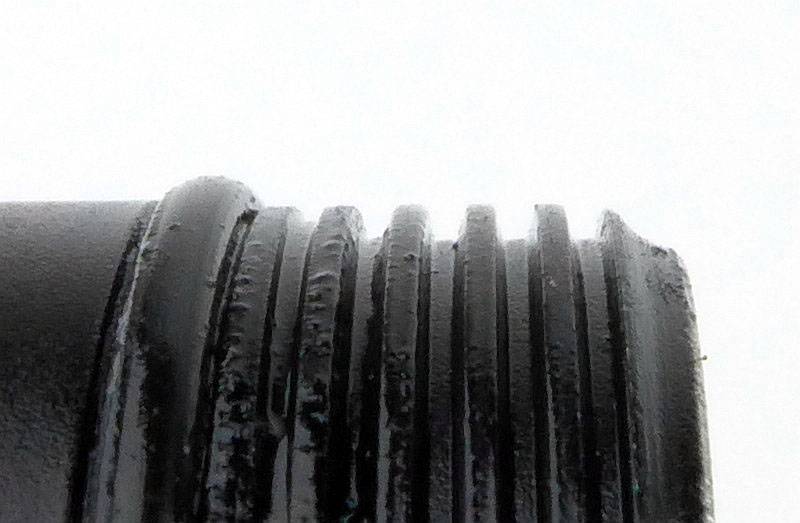
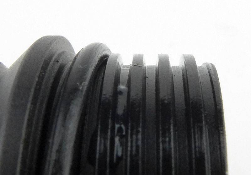
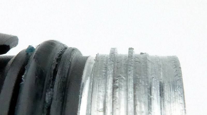
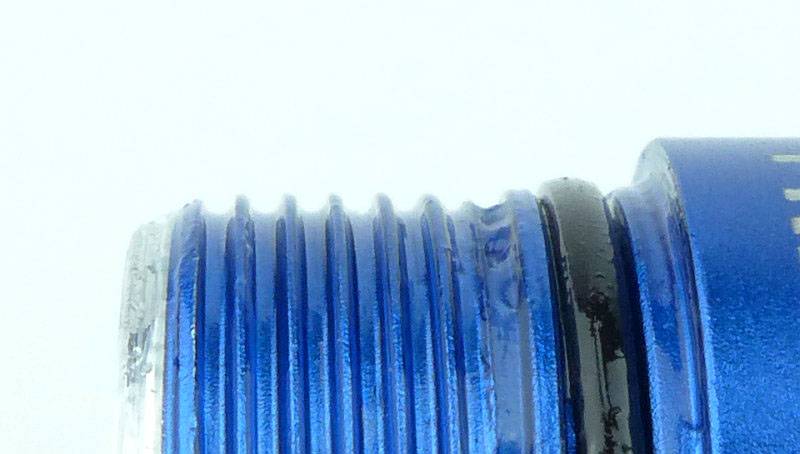
The threads are a standard form, and are well lubricated. (This is the same for the P1 so the P1 is not being shown.)
You can unscrew the switch cap and take the clip off, but this does not give access to the battery chamber.
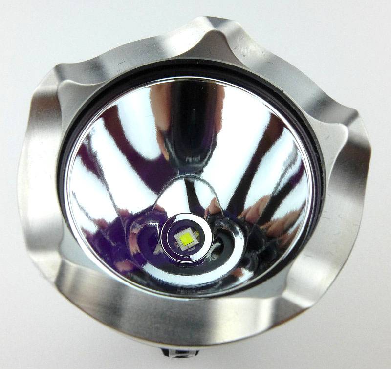
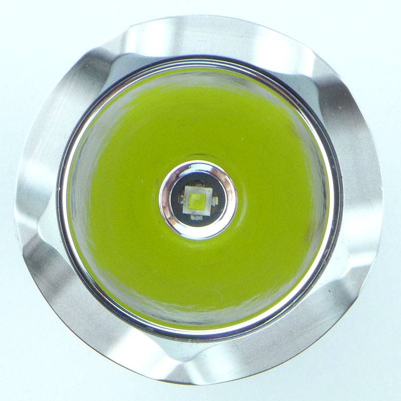
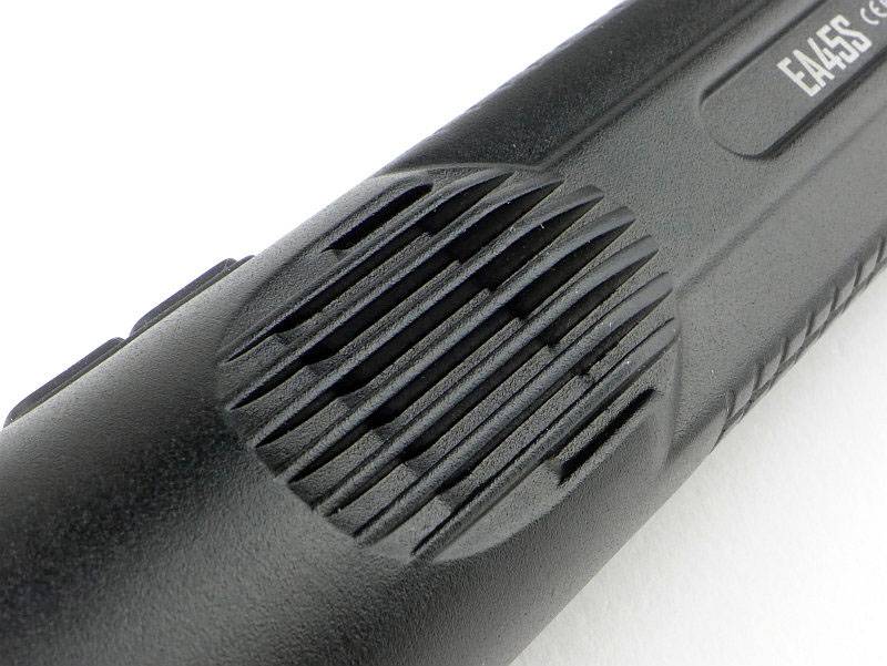
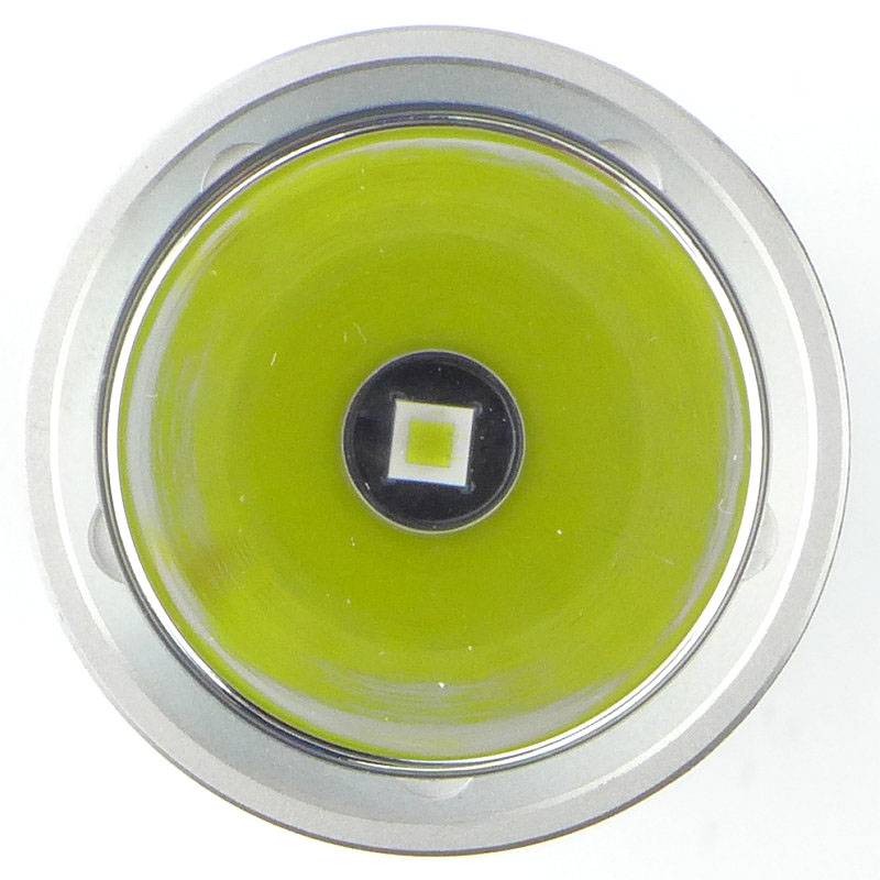
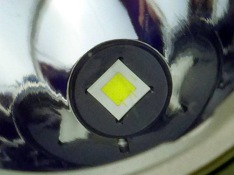
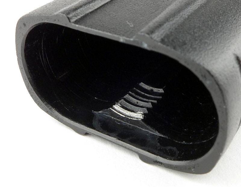
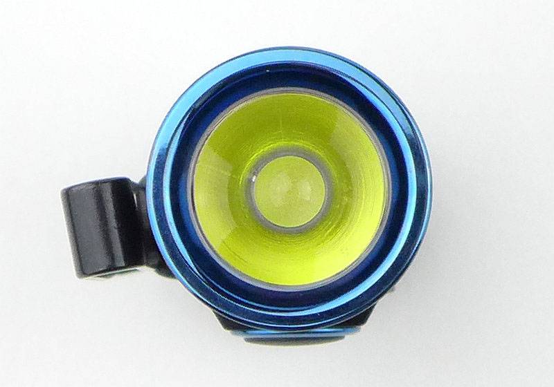
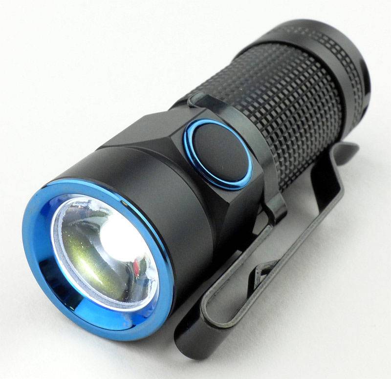
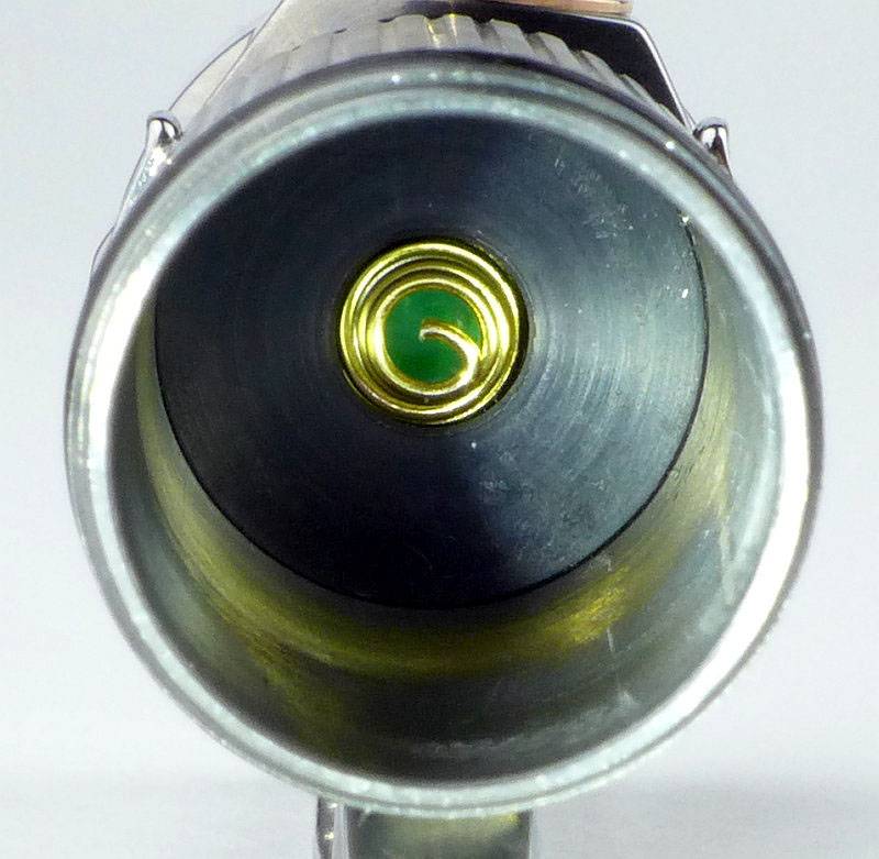
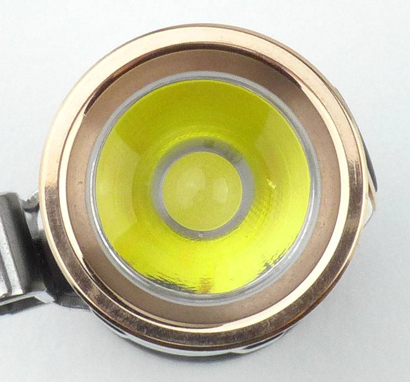
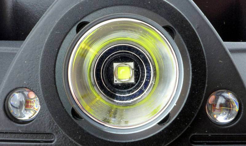
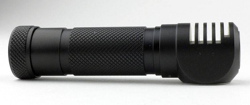
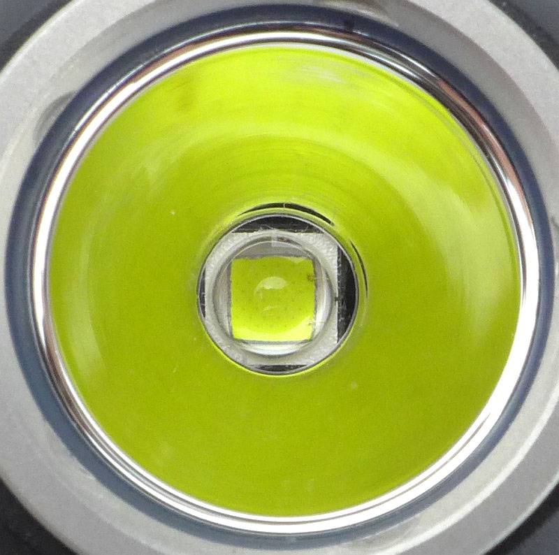
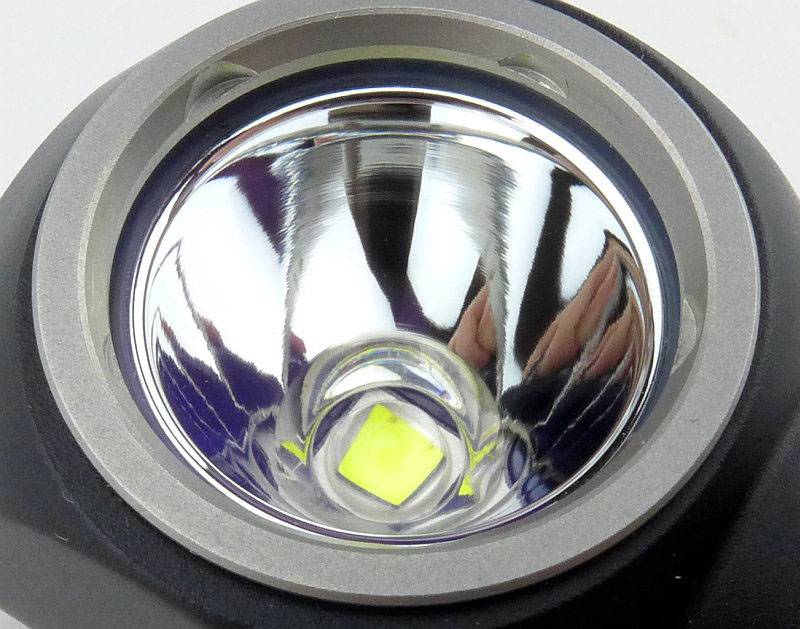
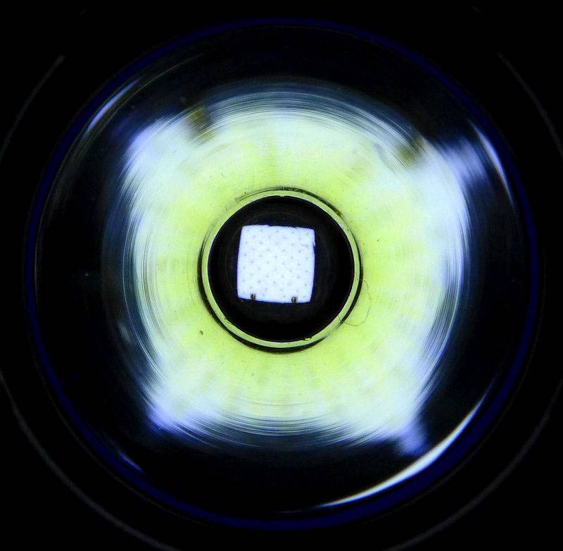
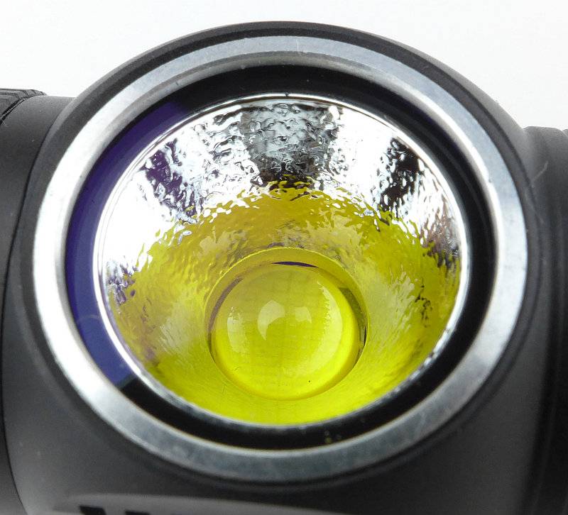
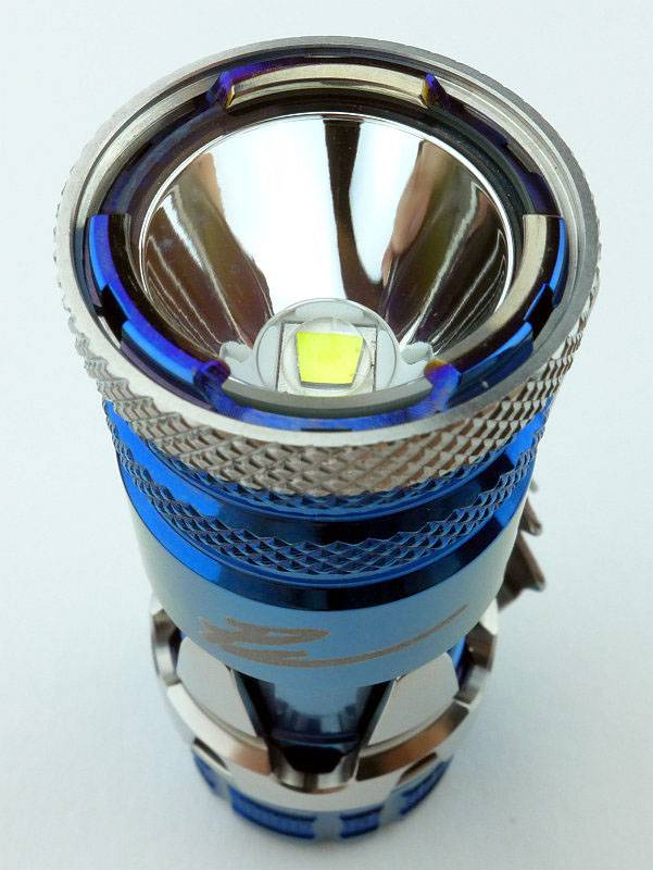
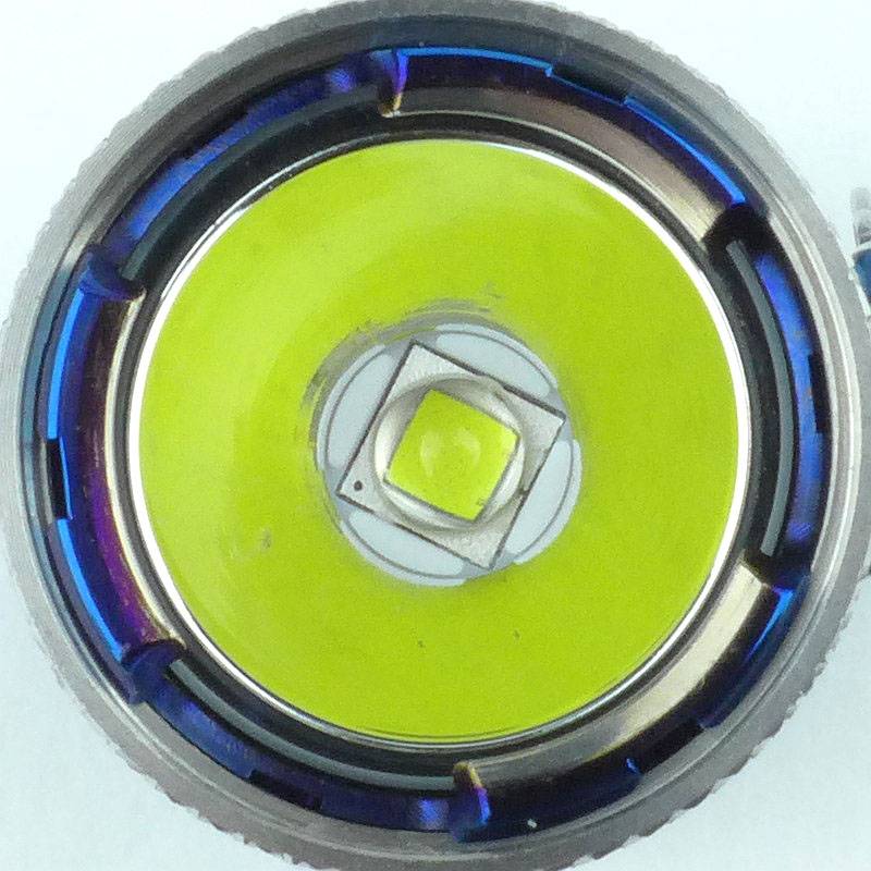
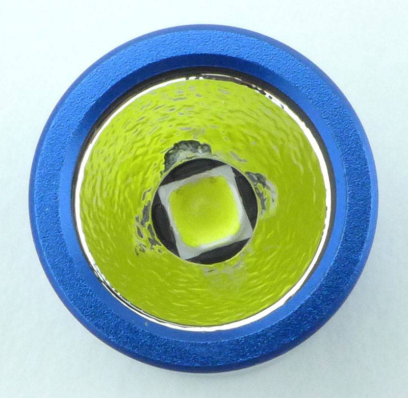
An XP-L LED sits in a small textured reflector.
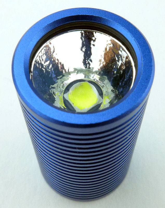
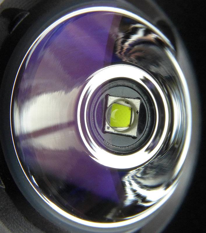
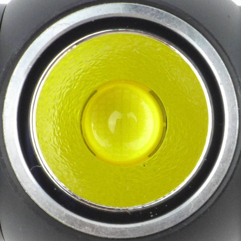
Looking straight into the small reflector.
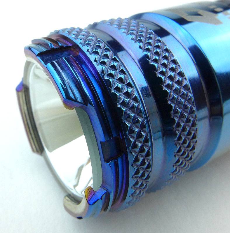
The clip on the P1 is the same, but here is a view from a different angle.
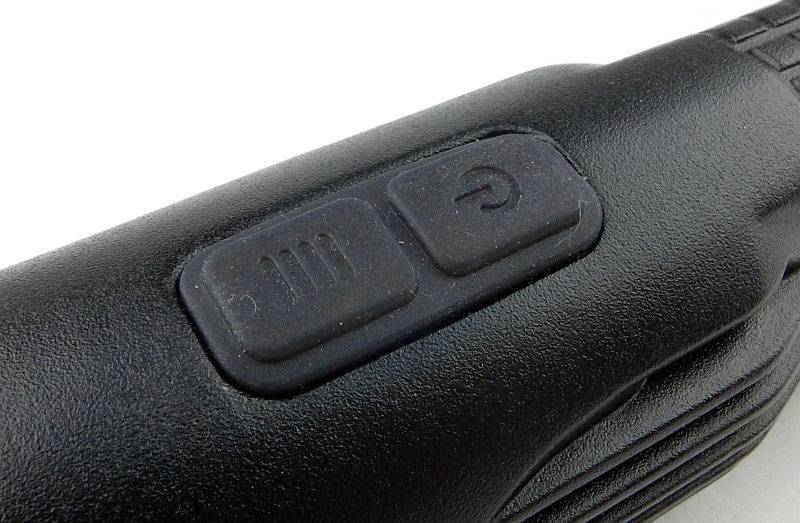
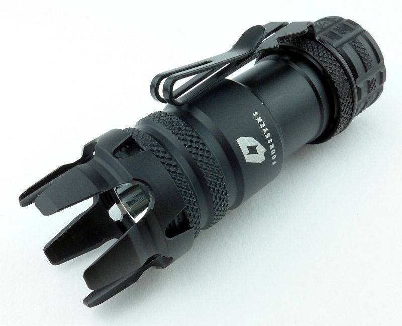
The P1 also has a metal switch cap over a forward-clicky switch.
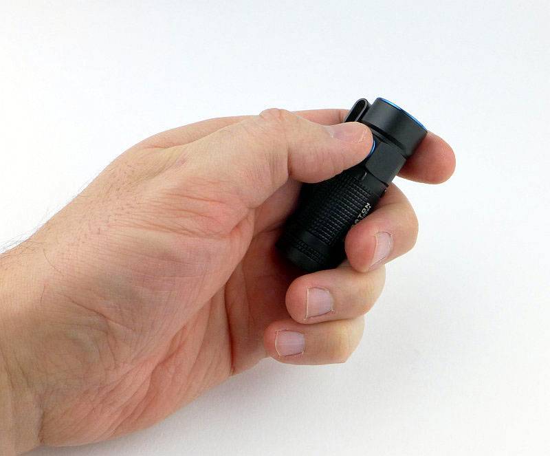
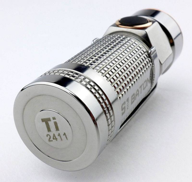
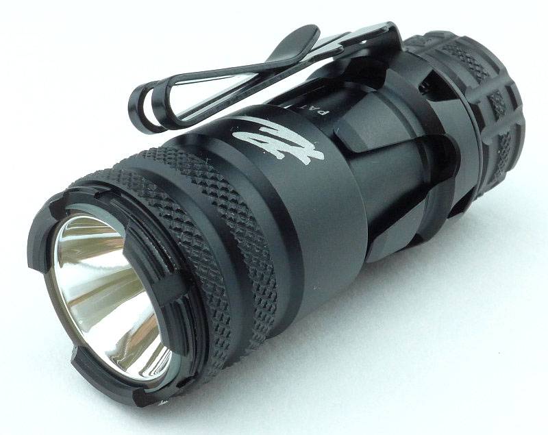
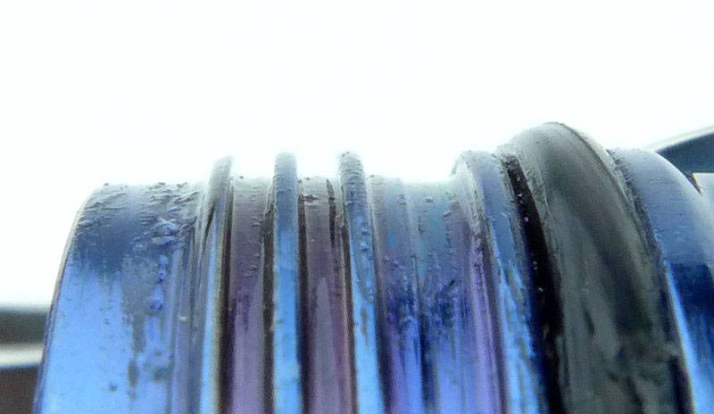
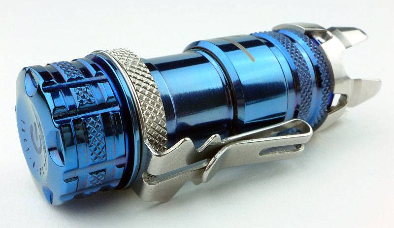
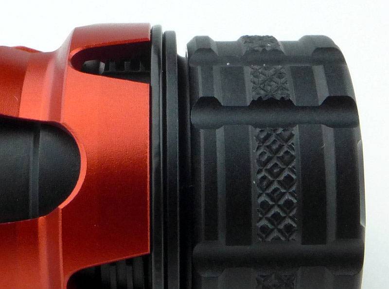
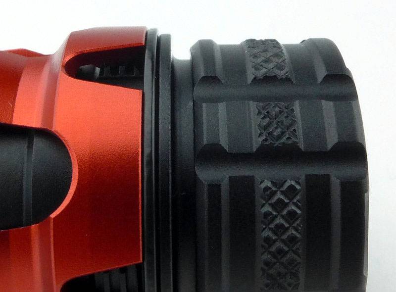
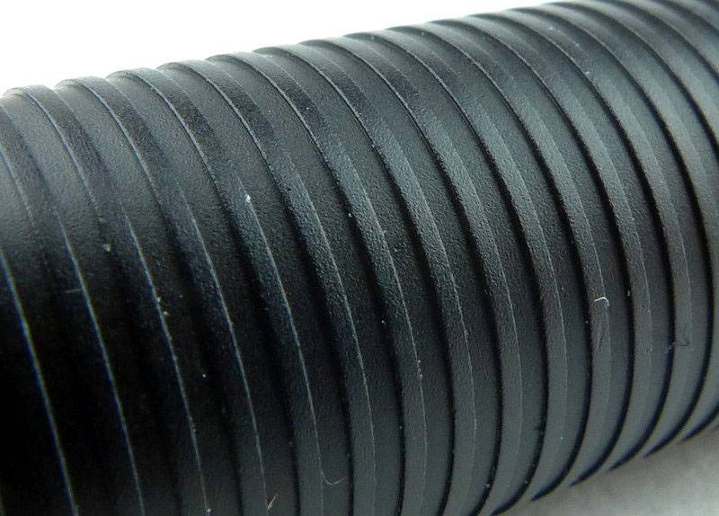
The new Preons feature a fully textured body with grooves for grip along the entire length.
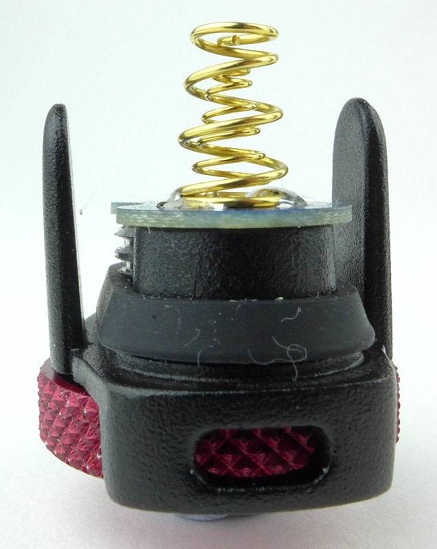
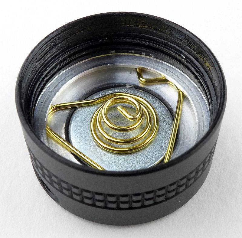
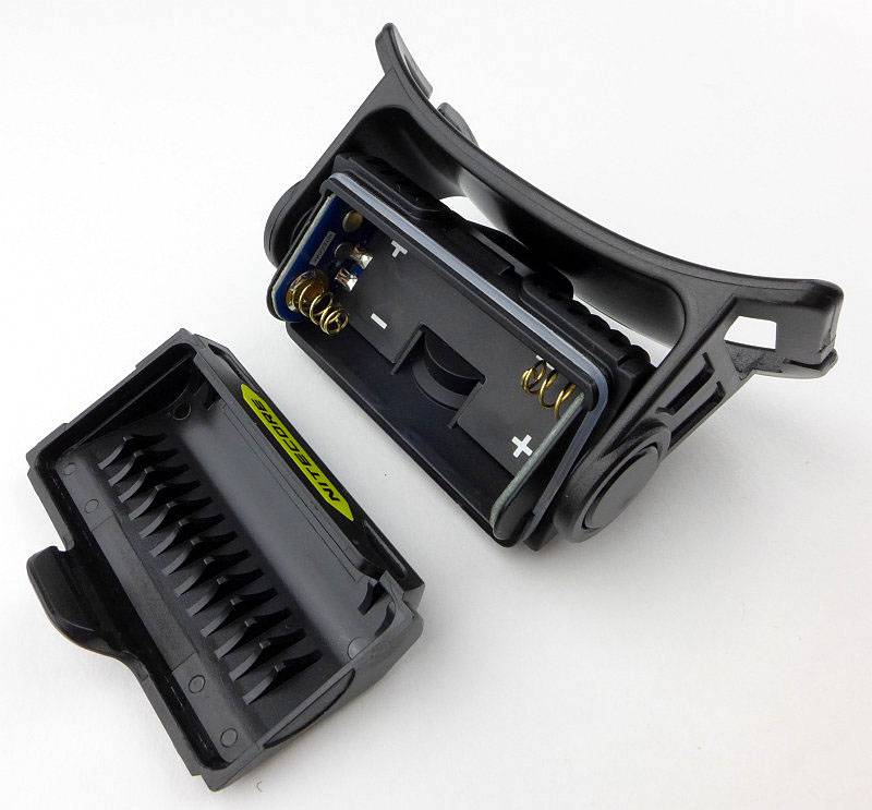
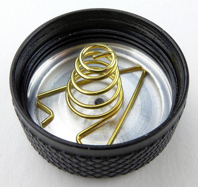
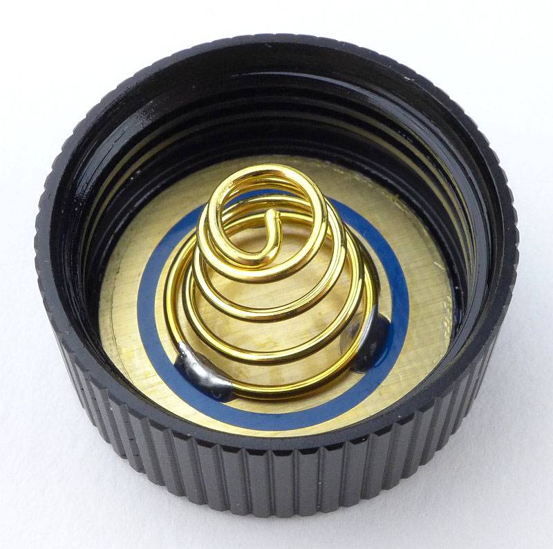
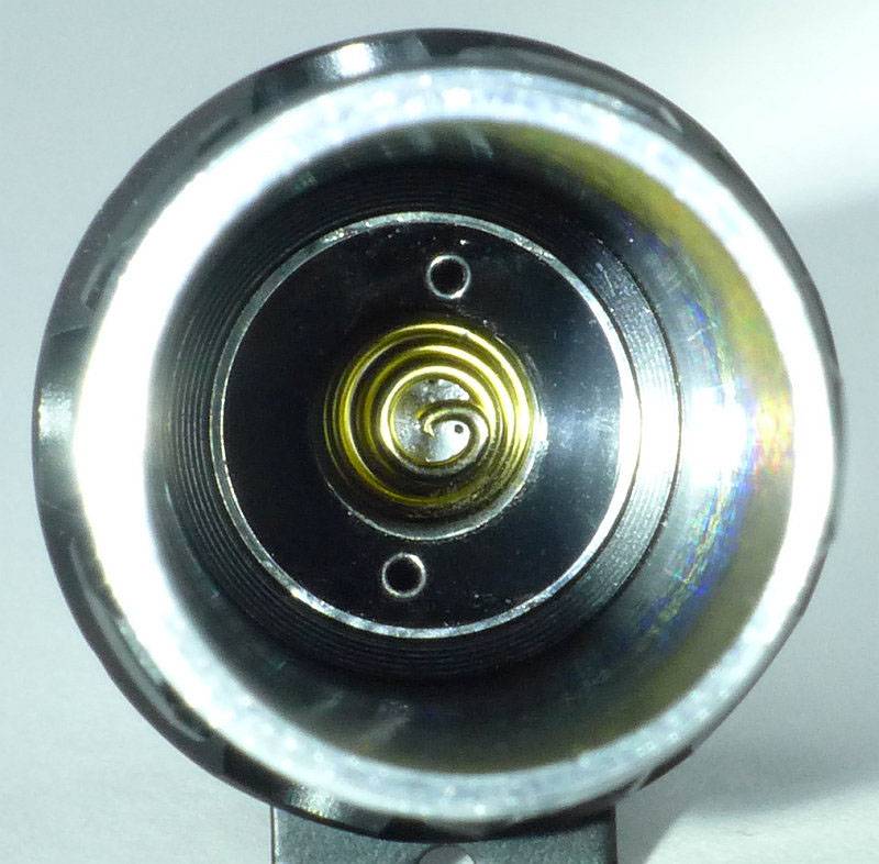
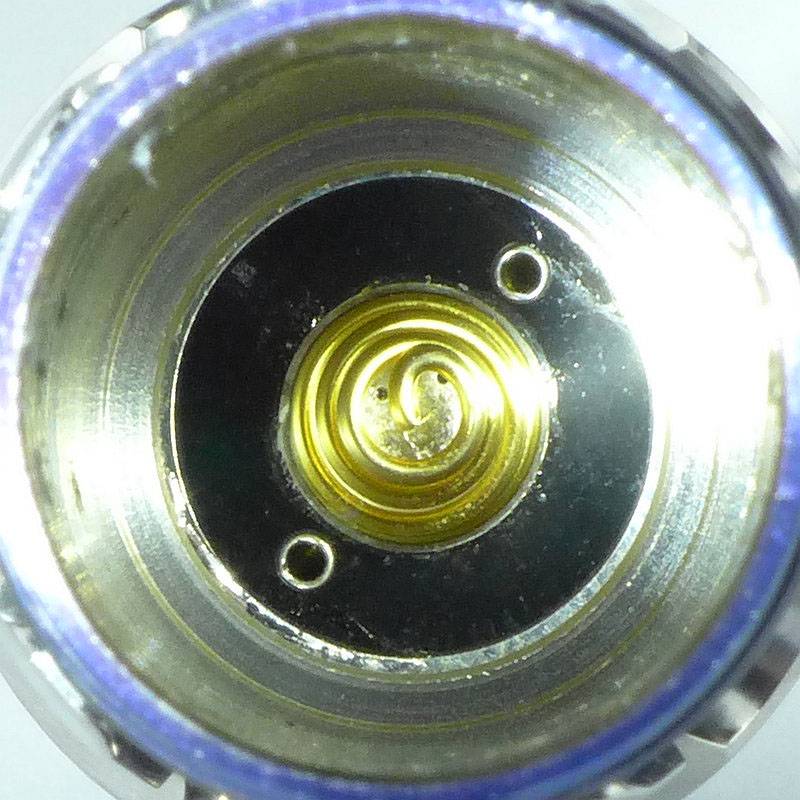
With it shorter battery tube it is just possible to show the positive contact spring terminal.
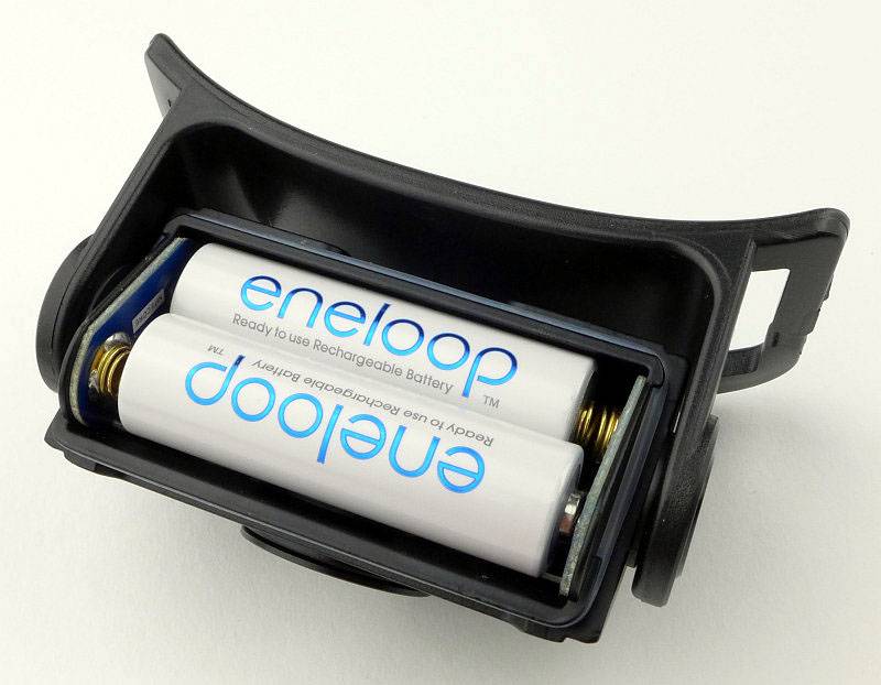
For scale, each Preon is shown with its AAA cells next to it.
The beam
Please be careful not to judge tint based on images you see on a computer screen. Unless properly calibrated, the screen itself will change the perceived tint.
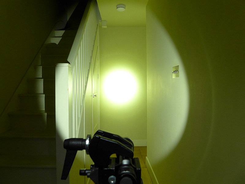
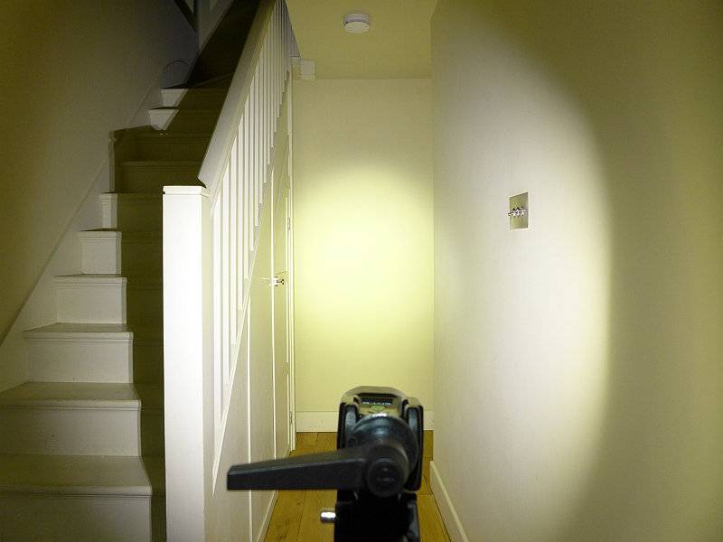
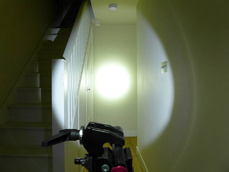
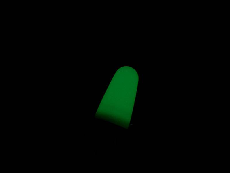
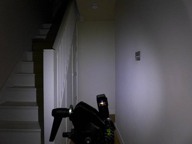
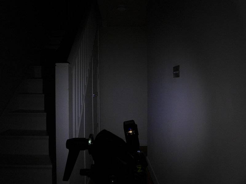
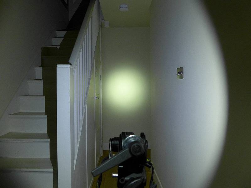
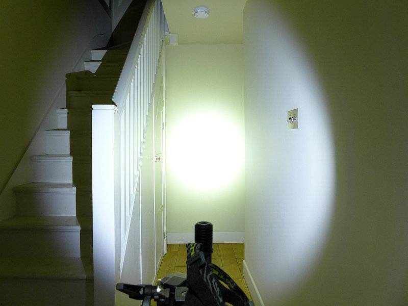
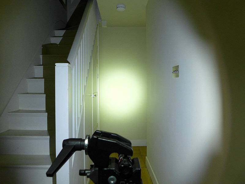
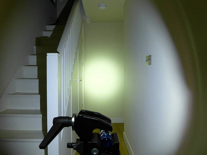
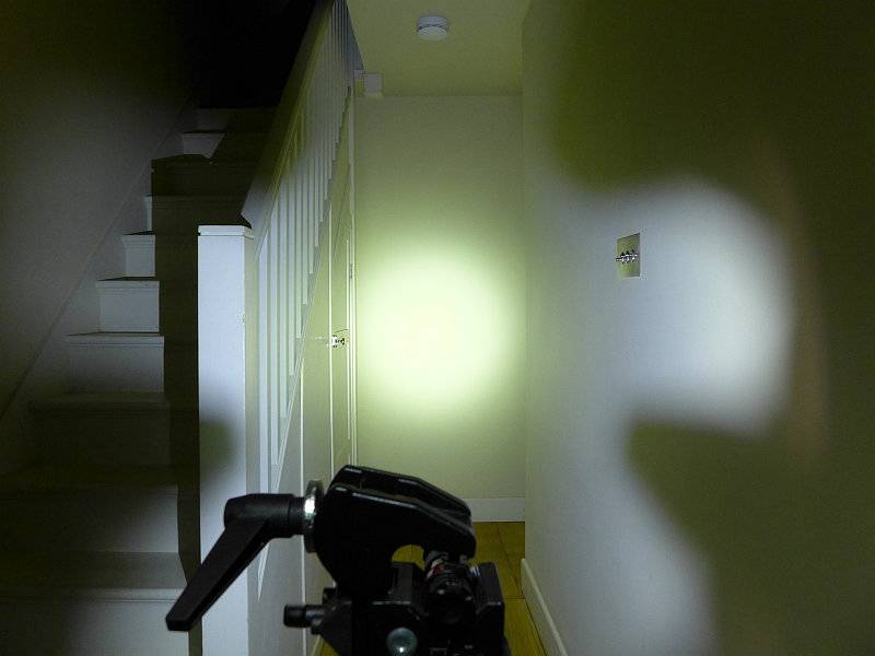
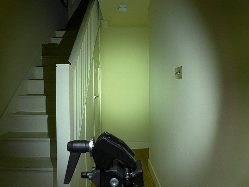
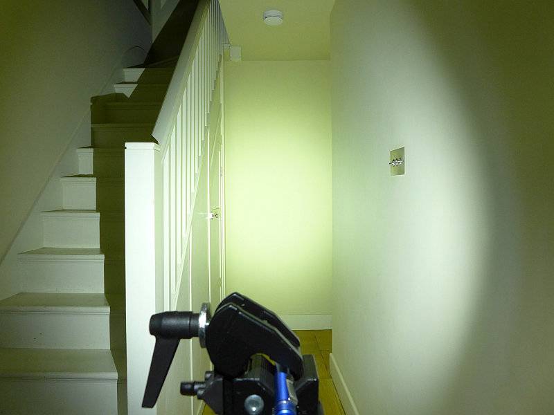
The indoor beamshot is intended to give an idea of the beam shape/quality rather than tint. All beamshots are taken using daylight white balance. The woodwork (stairs and skirting) are painted Farrow & Ball “Off-White”, and the walls are a light sandy colour called ‘String’ again by Farrow & Ball. I don’t actually have a ‘white wall’ in the house to use for this, and the wife won’t have one!
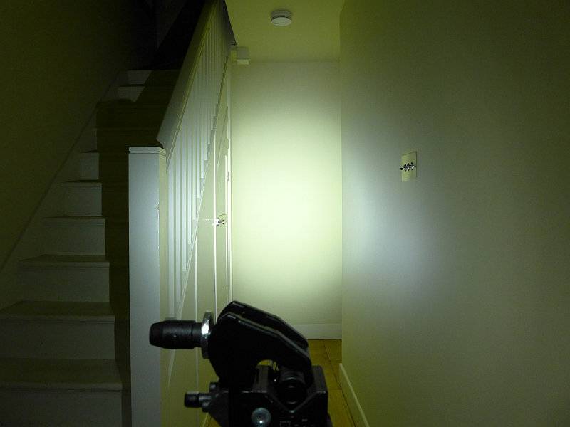
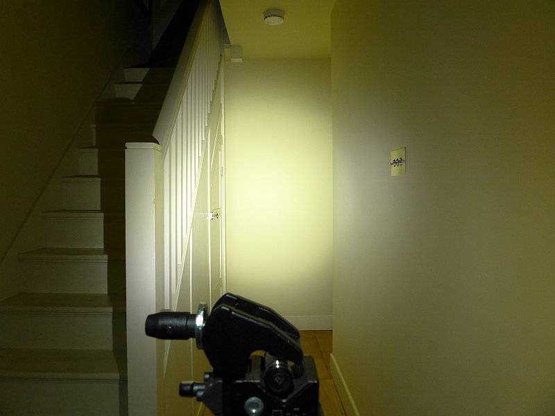
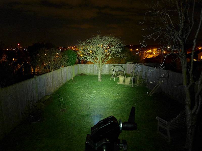
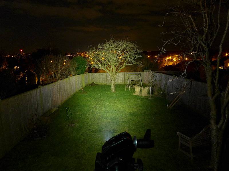
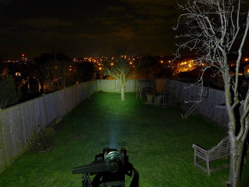
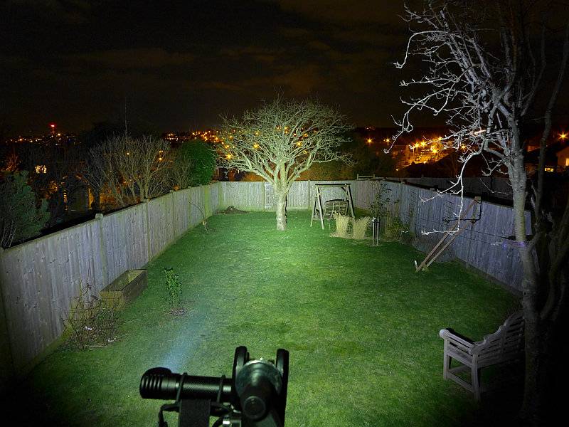
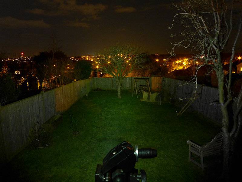
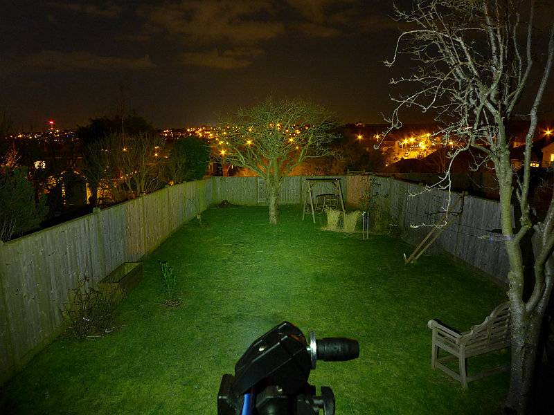
For this set of beamshots, the exposure has been kept the same for the P1 and P2 to show their relative brightness.
Starting indoors with the P1, it has plenty of power for your close range EDC needs, with a nice wide, soft, hotspot and wide spill.
With the P2 it looks the same just brighter, as the P2 has double the output of the P1.
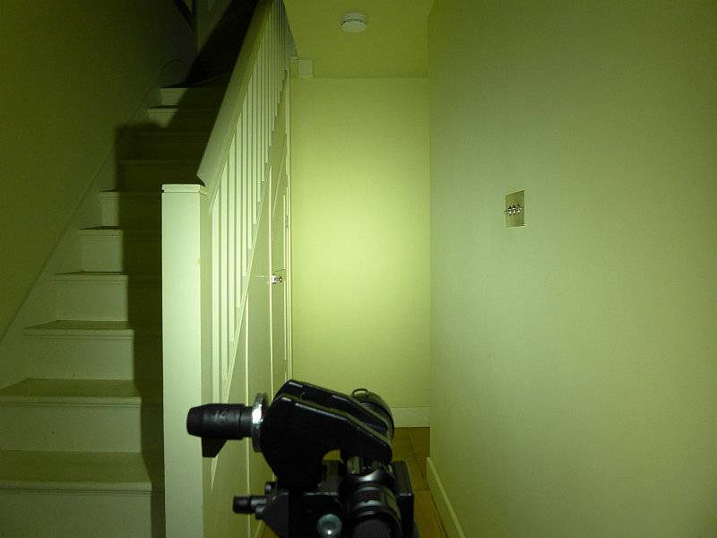
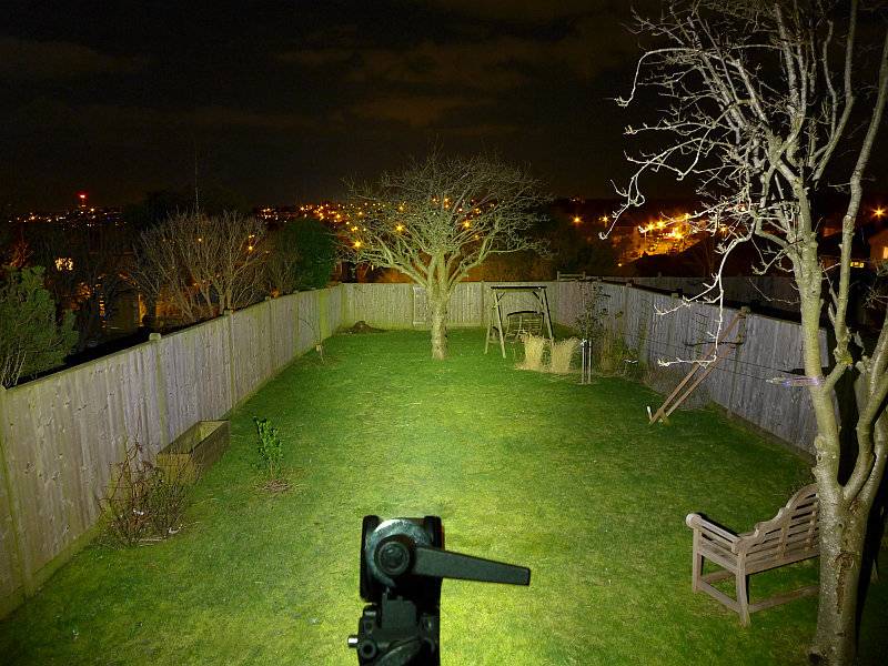
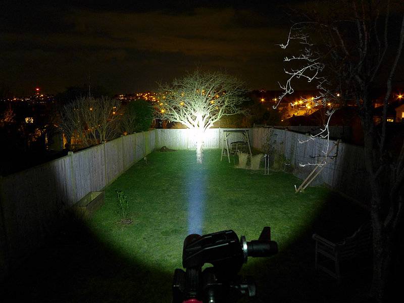
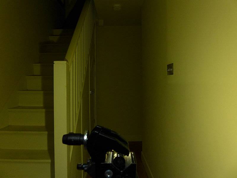
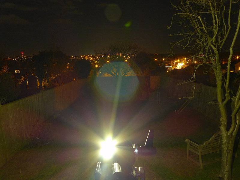
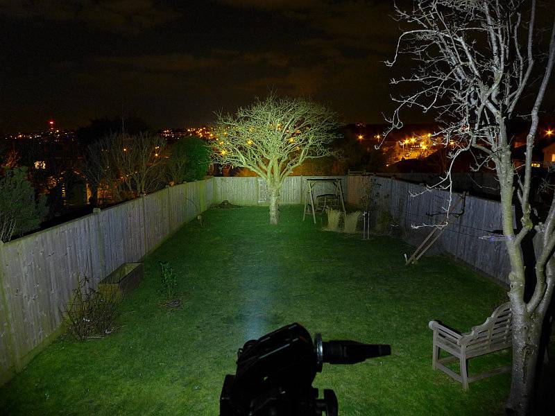
At outdoor ranges the Preons struggle as they are only AAA powered and have a flood orientated beam. These exposures are long to show anything. The P1 doesn’t have much impact.
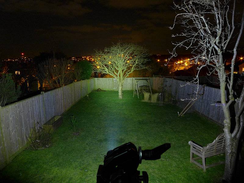
With the same exposure to allow direct comparison, the P2 looks a bit better, but this is a long exposure, so don’t expect too much at this range.
Modes and User Interface:
Both the Preon P1 and P2 operate in the same way with a forward-clicky switch.
In total, there are 7 output modes which can be used – Low, Medium, High, Strobe, SOS, Beacon (high), Beacon (low).
To fine tune the Preon to your needs, you can set one of 5 possible ‘Configurations’ which have only certain modes available:
Configuration 1: High
Configuration 2: Previous, High, Low
Configuration 3: Previous, High, Strobe
Configuration 4: Previous, Low, Medium, High, Strobe
Configuration 5: Previous, Low, Medium, High, Strobe, SOS, Beacon (high), Beacon (low)
By default, configuration 2 is set. To change configuration, rapidly press the switch 10 times within 2s, holding or clicking the tenth press.
At this point the Preon will flash 1 to 5 times to indicate the selected configuration.
Quickly turn the Preon OFF and ON again to move to the next configuration, and repeat until you have the desired configuration. To memorise the setting, turn the Preon OFF for 5 seconds.
The Preon has a memory of the last mode used. This is relevant only on Configurations 2, 3, 4 and 5.
To change to the next mode in the chosen configuration, turn the Preon OFF and ON again within one second.
As shown in the Configuration list above, when you first turn the Preon ON, you get the ‘previously used’ output mode. When you then change mode, you jump to the start of the set of modes for that Configuration.
For example, if you are set to Configuration 5 and previously used Strobe, when you first turn the Preon ON you get Strobe, and when changing modes the next mode becomes Low, Medium… (In this example you do not go to SOS as the next mode).
Batteries and output:
The Preon P1 runs on 1x AAA and the P2 on 2x AAA; either Alkaline of NiMh cells can be used (maximum input voltage 3.0V).
To measure actual output, I built an integrating sphere. See here for more detail. The sensor registers visible light only (so Infra-Red and Ultra-Violet will not be measured).
Please note, all quoted lumen figures are from a DIY integrating sphere, and according to ANSI standards. Although every effort is made to give as accurate a result as possible, they should be taken as an estimate only. The results can be used to compare outputs in this review and others I have published.
| ___________________________________________ | ________________________________ | ________________________________ |
| P1/P2 using AAA Eneloop | I.S. measured ANSI output Lumens | PWM frequency or Strobe frequency (Hz) |
| ___________________________________________ | ________________________________ | ________________________________ |
| P1 – High | 127 | 1000 |
| P1 – Medium | 63 | 1000 |
| P1 – Low | 7 | 1000 |
| P2 – High | 259 | 950 |
| P2 – Medium | 137 | 950 |
| P2 – Low | 33 | 950 |
* Beacon and Strobe output measurements are only estimates as the brief flashes make it difficult to capture the actual output value.
Peak Beam intensity for the P1 measured 200 lx @1m giving a beam range of 28 m.
Peak Beam intensity for the P2 measured 600 lx @1m giving a beam range of 49 m.
There is no parasitic drain.
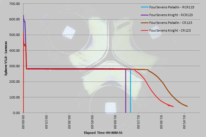
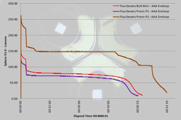
The two Preon models are also shown next to the Bolt-Mini, as this was another FOURSEVENS AAA light I have tested (check index page for this review). Thanks to its two AAA cells, the P2 is the only light to display full regulation in the output. With only one AAA, the P1 is always pushing this limited power source, but runs with a pretty consistent output after the initial drop from the 3 minute ‘burst’ at turn-on.
Troubleshooting
This section is included to mention any minor niggles I come across during testing, in case the information helps anyone else.
No issues were encountered during testing.
As per the description of this section, this information is provided in case anyone else finds a similar ‘issue’ that might be fixed in the same way.
The Preon P1 and P2 in use
When compared to the previous generation Preons, these new versions are slightly chunkier, and initially I was not entirely convinced, as the point of an AAA light is to be very small. But then I remembered that as much as I love the older P2 shown in the photos, it was always a bit slippery. The smooth body wanting to slide around and not giving much of a grip.
With the new Preons having a grip pattern over the entire length of the light, no longer do you get this slippery feeling. One further observation though, is that these grooves tend to pick up pocket fluff nicely, which does somewhat spoil the look.
Personally I preferred the previous UI where it had no memory, but for some a memory is a requirement as you can pre-select the output you generally use. However, as the memory only affects the mode at switch-on, after which the mode selection goes to the first of the modes in the current Configuration, it only takes one mode change to return to Low (if Low was not the previously used mode). On the P2, the Low is much brighter than it used to be (3lm in the previous version) as it is now 33lm. The P1’s low is still pretty low at 7lm so if you need a lower output the P1 is the way to go.
Unfortunately another aspect has changed in the new version, PWM is rearing its head. The previous P2 had PWM but at 2500Hz and was not noticeable to the naked eye; the new version has PWM at 1000Hz. On High and Medium this has not really been visible, but on Low, I do catch the strobing effect out of the corner of my eye. A minor irritation and not what I would expect of FOURSEVENS. It slightly takes the edge off what could be a great update to this well loved series.
It used to be more common for smaller EDC lights to go with a reverse-clicky switch, but as in earlier versions, the Preon does use a forward-clicky and gives you that immediate response to pressure on the switch.
A great feature that has been added to the Preons is the user-changeable configuration that allows you to limit which output modes can be selected. You don’t get to choose which modes are included in a ‘configuration’ but you can choose one of the five available ‘configurations’ to best suit your needs. This user configuration has great potential and I hope FOURSEVENS expand the number of configurations that can be chosen from including a lower level in the P2, and perhaps configurations with no memory. Remember when choosing your configuration that the new Preon has a memory so starts on the last used mode.
With the small power source of AAA, the added efficiency of the XP-L (though only around 9%) makes a difference. Thanks to the XP-L having an XM-L2 size die in a smaller package, it is compact enough to be fitted into the Preon’s head and provide a great EDC beam.
The new Preon doesn’t just have a new body design, it has user-configuration and an XP-L LED.
Review Summary
| _______________________________________________ | _______________________________________________ |
| Things I like | What doesn’t work so well for me |
| _______________________________________________ | _______________________________________________ |
| XP-L LED in a truly pocket-sized light. | PWM at 1000Hz giving some strobe effects on low. |
| New ‘grippy’ body design. | P2’s lowest level is a bit high at 33lm. |
| User configurable. | |
| Great EDC beam. |
Discussing the Review:
Please feel free to add comments to the review, but the ideal place to freely discuss these reviews is on a forum. If you started reading the shorter forum version of the review, but followed the link this full exclusive review, please return to that forum to discuss the review there.
If you read the review entirely on Tactical Reviews, please consider one of the following to join in any discussion.
CandlePowerForums – Flashlight Reviews Section (Largest and Friendliest Flashlight Community Forum)
EdgeMatters – Sponsored Reviews (UK based Forum for Knife Makers and Collectors)