Gear Review: Walkstool ‘Comfort 65’ Portable Stool with Telescopic Legs

It was at IWA 2016 that I came across Walkstool on my way to another appointment. As soon as I saw their telescopic folding stools I felt they were worth further investigation, and after a demonstration by Pius Schmitt (who is featured in the Walkstool website videos) didn’t need any further persuasion; I knew this was something special.

 photo 13 walkstool featured P1190526.jpg

A little more background:

Background, but not about Walkstool, instead about me and portable seating. Maybe it is a sign of age, or maybe just being in favour of comfort, but I’ve used some form of portable seating whenever I could carry it on various trips and outings.

These have included shooting sticks, many different folding chairs and lots of different folding stools. In all cases, the only telescopic part of any design was on a few shooting sticks to give some degree of height adjustment but no real saving in carried size.

The compromises in size and weight have always resulted in anything comfortable being large and heavy and not very portable, and anything small and light being really quite uncomfortable and generally too short for comfort.

At IWA I was not looking for anything like Walkstool’s Comfort (65cm model on test here), but it simply stood out. As soon as I saw that there were several different sizes, that the legs were telescopic (making them nearly 50% smaller when folded, and giving you two sitting heights) and the strong comfortable seat, the Walkstool had me interested.

The Walkstool family with the two Basic models on the left (made in China) and the four Comfort models (made in Sweden).
 photo ws_family_screen.jpg

A few more details:

Each Walkstool comes in a carry bag that can be carried over your shoulder.
 photo 01 walkstool bag P1180579.jpg

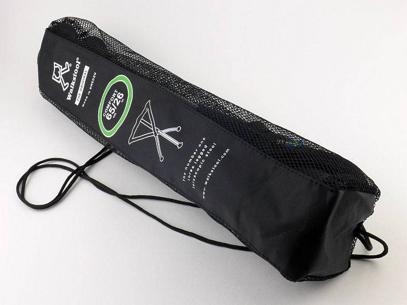
When folded it is an extremely neat package.
 photo 02 walkstool folded P1180580.jpg

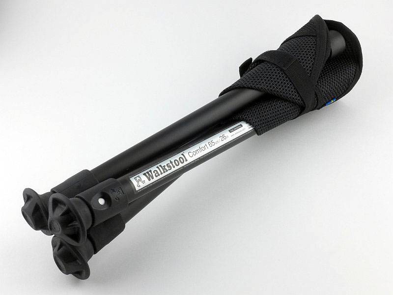
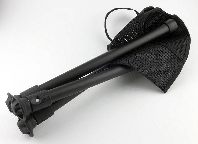
Wrapped round the seat is a strap with Velcro fastening to hold the stool tightly closed.
 photo 03 walkstool opening P1180584.jpg

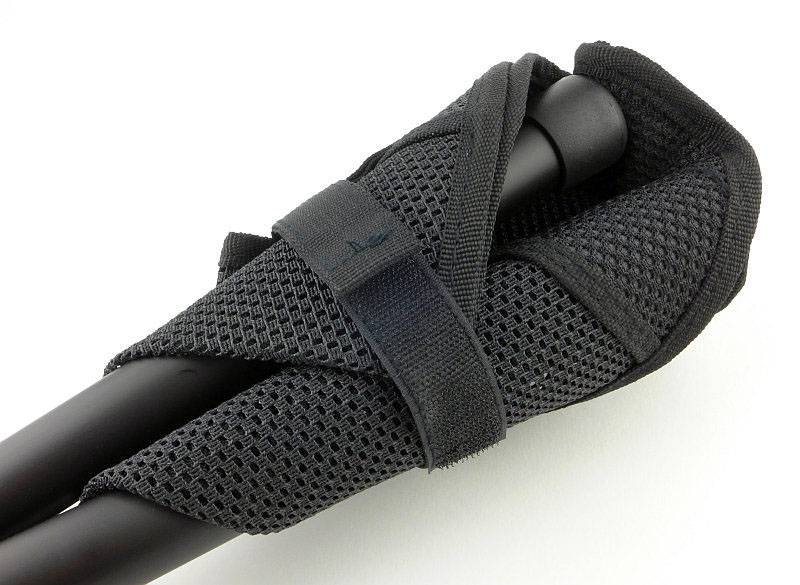
Just tear back the free end of the strap to open.
 photo 04 walkstool opening P1180585.jpg

Once released the seat material starts to open up
 photo 05 walkstool opening P1180587.jpg

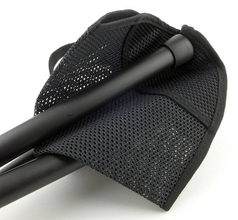
Strap released and ready to be opened.
 photo 06 walkstool opening P1180590.jpg

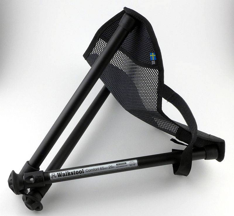
Opening out the seat, but not yet the legs. You can use the Walkstool in this configuration for a lower seating position, or to sit with a knee down to the ground.
 photo 07 walkstool half open P1180591.jpg

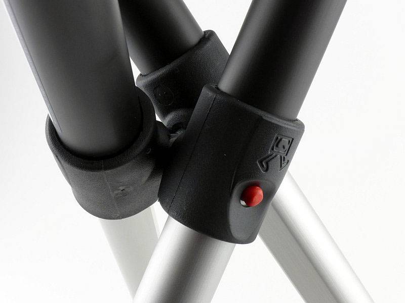
A special tri-bolt holds the legs together very strongly. Here you can see one of the leg release buttons (red) which is visible with the legs extended, and must be pressed in to allow the legs to retract. If you press the release button and pull the leg, you can remove it for cleaning.
 photo 08 walkstool detail leglocks P1180594.jpg

Ready to sit on the lower height.
 photo 10 walkstool half open P1180634.jpg

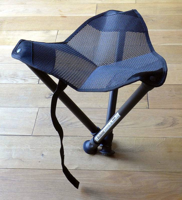
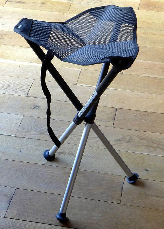
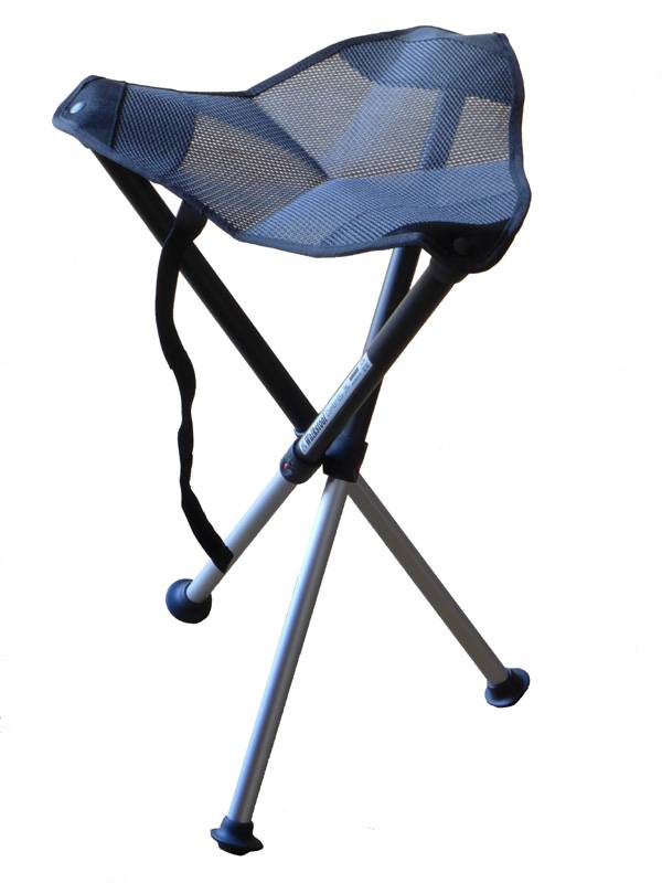
With legs extended you have a proper stool to sit on.
 photo 09 walkstool fully open P1180628.jpg

It is worth having a look at Walkstool’s video demonstration.

What it is like to use?

The first point to consider is that part of ‘using’ this stool is carrying it with you. It certainly is light enough to be an all day companion and you will want to take it with you rather than agonise over if it is worth the effort of carrying it.

I’ve carried it in three ways; firstly in the supplied bag, out of the bag and using the strap to secure it to my belt or a backpack, and finally actually fully inside a backpack.

Of these carry methods, my least favourite is using the carry bag. The strap is a string which has a tendency to want to slip off your shoulder. Not a design fault or problem, just a reason I would generally avoid this.

If I have a full size backpack I will simply pop the Walkstool inside the backpack, zip up and forget I have it with me until I want to use it. This is my preferred carry method.

Lastly the strap for folding up the Walkstool has intentionally been made longer than needed so that you can use this strap to attach it to something else. Walkstool show this being fixed to a belt, but I’ve also used it to attach the Walkstool to the outside of my backpack. Particularly useful if the backpack too small to fit the Walkstool fully inside. A minor annoyance on this subject though is that there is exposed ‘hook’ Velcro on the strap; this has a tendency to be very aggressive to other fabrics. I have used some Velcro ‘loop’ tape to cover this up, but it would be nice if this was included with the stool.

So many stools I’ve used in the past have been too short, and that makes you less stable and sitting on these becomes tiring. When looking at the Walkstool models I assumed I would find the tallest would suit me as I’m 6’2″ with relatively long legs. To my surprise, the Walkstool 75 (the largest) was too tall for me and it turns out the Comfort 65 was a much better match. If you can, try the different models, or at least consult the Walkstool size guide.

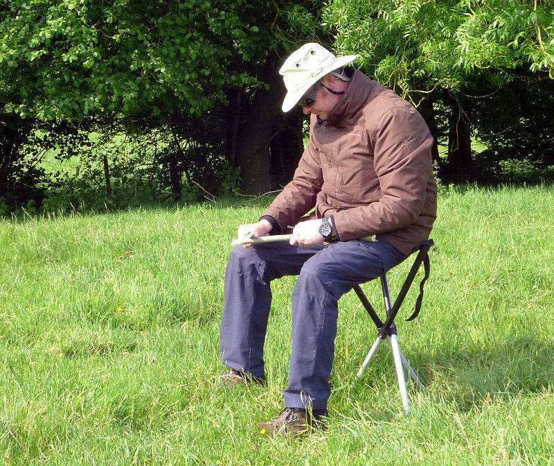
So you have it with you, and now it is time for a sit down. Extend the legs, open them out and sit in excellent comfort. I was doing a little whittling (with a Swedish knife, as it happens, the Fällkniven F1 Pro) and was perfectly comfortable and stable on the Walkstool.
 photo 13 walkstool featured P1190526.jpg

There are often instances where you want to be sitting lower, but not on the ground, perhaps if you are with a group of people not so well equipped who are sitting on the ground, or if you are working with several things and have them laid out on the ground.
Using the Walkstool with the legs retracted, you have this low height stool which can rock around the central point where the legs are connected, giving you mobility and the ability to turn.
 photo 12 walkstool sitting half open P1190529.jpg

Having this dual height is more useful than I thought it would be and is a unique feature made possible by the telescopic legs.

Quite simply I would not go back to anything else having used this folding stool, as nothing else I have ever seen provides so much comfort, quality and strength in such a small light package.

Review Summary

The views expressed in this summary table are from the point of view of the reviewer’s personal use. I am not a member of the armed forces and cannot comment on its use beyond a cutting tool or field/hunting knife.

Something that might be a ‘pro’ for one user can be a ‘con’ for another, so the comments are categorised based on my requirements. You should consider all points and if they could be beneficial to you.

_______________________________________________ _______________________________________________
Things I like What doesn’t work so well for me
_______________________________________________ _______________________________________________
Excellent comfort. More expensive than other folding stools.
Strong and stable. Exposed ‘hook’ Velcro tape.
Dual height. Potential for dirt to seize the telescopic legs (but legs are removable for cleaning).
Different sizes available.
Easy to carry.

See Walkstool’s Website for the sizing guide, Walkstools holding up a car and more. This review is included on the Walkstool Testimonial Page.


Discussing the Review:

Please feel free to add comments to the review, but the ideal place to freely discuss these reviews is on a forum. If you started reading the shorter forum version of the review, but followed the link this full exclusive review, please return to that forum to discuss the review there.
If you read the review entirely on Tactical Reviews, please consider one of the following to join in any discussion.

(You many need to use the forum’s ‘Search’ to find the review.)

EdgeMatters – Sponsored Reviews (UK based Forum for Knife Makers and Collectors)

CandlePowerForums (Largest and Friendliest Flashlight Community Forum)

Light Review: FOURSEVENS Preon P1 and P2

FOURSEVENS’ Preons have been very popular and well regarded AAA powered EDC lights. Being time for a reboot, here are the current updated versions of the Preon P1 and P2.

(And yes, they do have a high efficiency XP-L LED.)
 photo 09 Preon P2 angle LED P1160829.jpg

Taking a more detailed look:

Presentation is great with FOURSEVENS’ standard clear plastic box packaging.
 photo 01 Preon P1P2 boxed P1160796.jpg

Each Preon comes with one set of AAA Alkaline cells, two spare O-rings and the instructions.
 photo 02 Preon P1P2 unboxed P1160798.jpg

A quick look at the previous generation Preon P2 (in toxic green) with the latest generation Preon P1 and P2.
 photo 04 Preon P1P2 trio angle P1160808.jpg

A feature of the Preons is the metal switch button. Prior to anodising, this has been engraved with the FOURSEVENS logo.
 photo 05 Preon P2 switch engraving P1160815.jpg

The stainless steel pocket clip is a well finished and has a well-suited tension (not too stiff) to the size and weight.
 photo 06 Preon P2 clip P1160819.jpg

Just above the head of the light the FOURSEVENS logo is laser engraved through the anodising.
 photo 07 Preon P2 engraving P1160821.jpg

On the opposite side the model is engraved.
 photo 08 Preon P2 engraving2 P1160825.jpg

A view of the contacts inside the head. (This is the same for the P1 so the P1 is not being shown.)
 photo 10 Preon P2 head contact P1160831.jpg

The threads are a standard form, and are well lubricated. (This is the same for the P1 so the P1 is not being shown.)
 photo 11 Preon P2 threads P1160834.jpg

You can unscrew the switch cap and take the clip off, but this does not give access to the battery chamber.
 photo 12 Preon P2 switch cap off P1160837.jpg

An XP-L LED sits in a small textured reflector.
 photo 13 Preon P2 reflector P1160839.jpg

Looking straight into the small reflector.
 photo 14 Preon P2 LED P1160845.jpg

The clip on the P1 is the same, but here is a view from a different angle.
 photo 15 Preon P1 clip P1160848.jpg

The P1 also has a metal switch cap over a forward-clicky switch.
 photo 16 Preon P1 switch P1160854.jpg

The new Preons feature a fully textured body with grooves for grip along the entire length.
 photo 17 Preon P1 body P1160855.jpg

With it shorter battery tube it is just possible to show the positive contact spring terminal.
 photo 18 Preon P1 negative terminal P1160864.jpg

For scale, each Preon is shown with its AAA cells next to it.
 photo 19 Preon P1P2 size P1160870.jpg

The beam

Please be careful not to judge tint based on images you see on a computer screen. Unless properly calibrated, the screen itself will change the perceived tint.

The indoor beamshot is intended to give an idea of the beam shape/quality rather than tint. All beamshots are taken using daylight white balance. The woodwork (stairs and skirting) are painted Farrow & Ball “Off-White”, and the walls are a light sandy colour called ‘String’ again by Farrow & Ball. I don’t actually have a ‘white wall’ in the house to use for this, and the wife won’t have one!

For this set of beamshots, the exposure has been kept the same for the P1 and P2 to show their relative brightness.

Starting indoors with the P1, it has plenty of power for your close range EDC needs, with a nice wide, soft, hotspot and wide spill.
 photo 20 Preon P1 indoor beam P1170374.jpg

With the P2 it looks the same just brighter, as the P2 has double the output of the P1.
 photo 21 Preon P2 indoor beam P1170370.jpg

At outdoor ranges the Preons struggle as they are only AAA powered and have a flood orientated beam. These exposures are long to show anything. The P1 doesn’t have much impact.
 photo 22 Preon P1 outdoor beam P1170293.jpg

With the same exposure to allow direct comparison, the P2 looks a bit better, but this is a long exposure, so don’t expect too much at this range.
 photo 23 Preon P2 outdoor beam P1170285.jpg

Modes and User Interface:

Both the Preon P1 and P2 operate in the same way with a forward-clicky switch.
In total, there are 7 output modes which can be used – Low, Medium, High, Strobe, SOS, Beacon (high), Beacon (low).

To fine tune the Preon to your needs, you can set one of 5 possible ‘Configurations’ which have only certain modes available:
Configuration 1: High
Configuration 2: Previous, High, Low
Configuration 3: Previous, High, Strobe
Configuration 4: Previous, Low, Medium, High, Strobe
Configuration 5: Previous, Low, Medium, High, Strobe, SOS, Beacon (high), Beacon (low)

By default, configuration 2 is set. To change configuration, rapidly press the switch 10 times within 2s, holding or clicking the tenth press.
At this point the Preon will flash 1 to 5 times to indicate the selected configuration.
Quickly turn the Preon OFF and ON again to move to the next configuration, and repeat until you have the desired configuration. To memorise the setting, turn the Preon OFF for 5 seconds.

The Preon has a memory of the last mode used. This is relevant only on Configurations 2, 3, 4 and 5.
To change to the next mode in the chosen configuration, turn the Preon OFF and ON again within one second.
As shown in the Configuration list above, when you first turn the Preon ON, you get the ‘previously used’ output mode. When you then change mode, you jump to the start of the set of modes for that Configuration.
For example, if you are set to Configuration 5 and previously used Strobe, when you first turn the Preon ON you get Strobe, and when changing modes the next mode becomes Low, Medium… (In this example you do not go to SOS as the next mode).

Batteries and output:

The Preon P1 runs on 1x AAA and the P2 on 2x AAA; either Alkaline of NiMh cells can be used (maximum input voltage 3.0V).

To measure actual output, I built an integrating sphere. See here for more detail. The sensor registers visible light only (so Infra-Red and Ultra-Violet will not be measured).

Please note, all quoted lumen figures are from a DIY integrating sphere, and according to ANSI standards. Although every effort is made to give as accurate a result as possible, they should be taken as an estimate only. The results can be used to compare outputs in this review and others I have published.

___________________________________________ ________________________________ ________________________________
P1/P2 using AAA Eneloop I.S. measured ANSI output Lumens PWM frequency or Strobe frequency (Hz)
___________________________________________ ________________________________ ________________________________
P1 – High 127 1000
P1 – Medium 63 1000
P1 – Low 7 1000
P2 – High 259 950
P2 – Medium 137 950
P2 – Low 33 950

* Beacon and Strobe output measurements are only estimates as the brief flashes make it difficult to capture the actual output value.

Peak Beam intensity for the P1 measured 200 lx @1m giving a beam range of 28 m.
Peak Beam intensity for the P2 measured 600 lx @1m giving a beam range of 49 m.

There is no parasitic drain.

The two Preon models are also shown next to the Bolt-Mini, as this was another FOURSEVENS AAA light I have tested (check index page for this review). Thanks to its two AAA cells, the P2 is the only light to display full regulation in the output. With only one AAA, the P1 is always pushing this limited power source, but runs with a pretty consistent output after the initial drop from the 3 minute ‘burst’ at turn-on.
 photo Foursevens Bolt mini Preon P1 P2 runtime.jpg

Troubleshooting

This section is included to mention any minor niggles I come across during testing, in case the information helps anyone else.

No issues were encountered during testing.

As per the description of this section, this information is provided in case anyone else finds a similar ‘issue’ that might be fixed in the same way.

The Preon P1 and P2 in use

When compared to the previous generation Preons, these new versions are slightly chunkier, and initially I was not entirely convinced, as the point of an AAA light is to be very small. But then I remembered that as much as I love the older P2 shown in the photos, it was always a bit slippery. The smooth body wanting to slide around and not giving much of a grip.

With the new Preons having a grip pattern over the entire length of the light, no longer do you get this slippery feeling. One further observation though, is that these grooves tend to pick up pocket fluff nicely, which does somewhat spoil the look.

Personally I preferred the previous UI where it had no memory, but for some a memory is a requirement as you can pre-select the output you generally use. However, as the memory only affects the mode at switch-on, after which the mode selection goes to the first of the modes in the current Configuration, it only takes one mode change to return to Low (if Low was not the previously used mode). On the P2, the Low is much brighter than it used to be (3lm in the previous version) as it is now 33lm. The P1’s low is still pretty low at 7lm so if you need a lower output the P1 is the way to go.

Unfortunately another aspect has changed in the new version, PWM is rearing its head. The previous P2 had PWM but at 2500Hz and was not noticeable to the naked eye; the new version has PWM at 1000Hz. On High and Medium this has not really been visible, but on Low, I do catch the strobing effect out of the corner of my eye. A minor irritation and not what I would expect of FOURSEVENS. It slightly takes the edge off what could be a great update to this well loved series.

It used to be more common for smaller EDC lights to go with a reverse-clicky switch, but as in earlier versions, the Preon does use a forward-clicky and gives you that immediate response to pressure on the switch.

A great feature that has been added to the Preons is the user-changeable configuration that allows you to limit which output modes can be selected. You don’t get to choose which modes are included in a ‘configuration’ but you can choose one of the five available ‘configurations’ to best suit your needs. This user configuration has great potential and I hope FOURSEVENS expand the number of configurations that can be chosen from including a lower level in the P2, and perhaps configurations with no memory. Remember when choosing your configuration that the new Preon has a memory so starts on the last used mode.

With the small power source of AAA, the added efficiency of the XP-L (though only around 9%) makes a difference. Thanks to the XP-L having an XM-L2 size die in a smaller package, it is compact enough to be fitted into the Preon’s head and provide a great EDC beam.

The new Preon doesn’t just have a new body design, it has user-configuration and an XP-L LED.

Review Summary

_______________________________________________ _______________________________________________
Things I like What doesn’t work so well for me
_______________________________________________ _______________________________________________
XP-L LED in a truly pocket-sized light. PWM at 1000Hz giving some strobe effects on low.
New ‘grippy’ body design. P2’s lowest level is a bit high at 33lm.
User configurable.
Great EDC beam.


Discussing the Review:

Please feel free to add comments to the review, but the ideal place to freely discuss these reviews is on a forum. If you started reading the shorter forum version of the review, but followed the link this full exclusive review, please return to that forum to discuss the review there.
If you read the review entirely on Tactical Reviews, please consider one of the following to join in any discussion.

CandlePowerForums – Flashlight Reviews Section (Largest and Friendliest Flashlight Community Forum)

EdgeMatters – Sponsored Reviews (UK based Forum for Knife Makers and Collectors)

Light Review: Olight M23 JAVELOT

Olight have taken the popular M22 Warrior and updated it by giving it the ‘JAVELOT’ treatment. The result is the M23 JAVELOT. After the success of the first few Javelot models, Olight have been updating a few existing models, like the S30RII and M22 into Javelot versions with uprated emitters and throw.

 photo 09 M23Javelot angle reverse P1160532.jpg

Taking a more detailed look:

The M23 JAVELOT is supplied in a sturdy plastic case.
 photo 01 M23Javelot boxed P1160500.jpg

Everything is held in cut-outs in the foam liner.
 photo 02 M23Javelot box open P1160506.jpg

Starting off with a look at the unconventional holster design. The retention flap has a hole cut into it through which the tail-cap protrudes. This gives access to the tail-cap switch.
 photo 03 M23Javelot holstered P1160512.jpg

Both sides of the holster feature cell holders. For CR123 these are not that secure, but for 18650 they work well enough (though the cell is partly exposed and could be damaged.
 photo 04 M23Javelot holster cells P1160513.jpg

Now we see why you might want access to the tail-cap switch while the light is in the holster. The bottom of the holster has a hole cut in it allowing the M23 to be used while fully inside the holster.
 photo 05 M23Javelot holster base P1160517.jpg

On the back is a Velcro belt-loop and small D-ring.
 photo 06 M23Javelot holster loop P1160519.jpg

Supplied with the M23 is the holster, CR123 cell holder, diffuser, spare O-rings, a lanyard, the instructions and two CR123 cells.
 photo 07 M23Javelot contents P1160526.jpg

Externally the main difference between the M22 Warrior and the M23 JAVELOT is the stainless steel bezel.
 photo 08 M23Javelot angle P1160528.jpg

The entire head has heat-sink fins along it.
 photo 10 M23Javelot heat sink fins P1160534.jpg

A side view of the steel pocket clip.
 photo 11 M23Javelot clip1 P1160537.jpg

Another view of the strong pocket clip.
 photo 12 M23Javelot clip2 P1160539.jpg

The pocket clip fits into a cut-out on the battery tube, and the grip-ring has a notch in it which fits over a lug on the steel pocket clip. This prevents the pocket clip or grip-ring rotating.
 photo 20 M23Javelot clip fitting P1160564.jpg

With the supplied diffuser fitted, the stainless bezel is hidden. You can’t fit the M23 into its holster like this.
 photo 14 M23Javelot angle diffuser P1160544.jpg

Inside the tail-cap, the negative terminal is a sprung plunger. The tail-cap/battery tube connection is hidden and uses a special design to fit into the conical opening at the end of the battery tube.
 photo 15 M23Javelot tailcap P1160548.jpg

The switch is large and textured.
 photo 16 M23Javelot tailcap switch P1160550.jpg

Threads on the tail-cap end of the battery tube are square cut and fully anodised.
 photo 17 M23Javelot threads P1160555.jpg

Threads on the head end of the battery tube are square cut and bare aluminium.
 photo 18 M23Javelot head threads P1160556.jpg

Unscrewing the battery tube fully shows the contacts in the head, with the positive spring-terminal, bare threads plus ring-terminal for the twisty interface.
 photo 19 M23Javelot head contacts P1160561.jpg

For its excellent throw the M23 uses a deep, smooth reflector.
 photo 21 M23Javelot reflector P1160574.jpg

Looking straight into the reflector.
 photo 22 M23Javelot LED P1160580.jpg

And a closer look at that LED. Olight describe this as a ‘customised high intensity CREE XP-L LED’.
 photo 23 M23Javelot LED close P1160586.jpg

The beam

Please be careful not to judge tint based on images you see on a computer screen. Unless properly calibrated, the screen itself will change the perceived tint.

The indoor beamshot is intended to give an idea of the beam shape/quality rather than tint. All beamshots are taken using daylight white balance. The woodwork (stairs and skirting) are painted Farrow & Ball “Off-White”, and the walls are a light sandy colour called ‘String’ again by Farrow & Ball. I don’t actually have a ‘white wall’ in the house to use for this, and the wife won’t have one!

The beam does have a reasonably warm tint and as expected for a JAVELOT light, there is a very strong hotspot. This might be a bit fatiguing to use indoors which is why there is a diffuser supplied.
 photo 24 M23Javelot indoor beam P1170305.jpg

Popping on the diffuser and we have an entirely different experience (the exposure here is the same as without the diffuser).
 photo 25 M23Javelot indoor beam diffused P1170308.jpg

Outdoors it is clear this is a thrower!
 photo 26 M23Javelot outdoor beam P1170240.jpg

And just to see, the result with the diffuser is good (the exposure here is the same as without the diffuser).
 photo 27 M23Javelot outdoor beam diffused P1170243.jpg

But we need more range, so here we are at a golf driving range with the 250yard marker easily visible, and beyond.
 photo 28 M23Javelot outdoor beam golf P1170221.jpg

Modes and User Interface:

The M23’s output is controlled by the forward-clicky tail-cap switch and twisty interface at the head.

Available modes include High, Medium, Low and Strobe.

From OFF, either click or half-press and hold to turn onto the last-used constant output mode.
From ON, either click the switch or release the half-press to turn OFF.

From OFF, double-tap and click (or hold) the switch to activate High.
From OFF, triple-tap and click (or hold) the switch to activate Strobe. While strobe is activated, the twisty interface does nothing.

From ON, loosen-tighten the head to cycle through High -> Medium -> Low -> High etc. (it is as the head becomes tight again that the mode changes). Tightening the head while the M23 is OFF does nothing.

This operation allows you to set the output to Low, but still have direct access to High (double-tap) and Strobe (triple-tap) via the tail-cap switch alone.

Batteries and output:

The M23 runs on either 1x 18650 or 2x CR123.

To measure actual output, I built an integrating sphere. See here for more detail. The sensor registers visible light only (so Infra-Red and Ultra-Violet will not be measured).

Please note, all quoted lumen figures are from a DIY integrating sphere, and according to ANSI standards. Although every effort is made to give as accurate a result as possible, they should be taken as an estimate only. The results can be used to compare outputs in this review and others I have published.

___________________________________________ ________________________________ ________________________________
Olight M23 JAVELOT using specified cell I.S. measured ANSI output Lumens PWM frequency or Strobe frequency (Hz)
___________________________________________ ________________________________ ________________________________
High – CR123 950 0
Medium – CR123 361 0
Low – CR123 38 0
High – 18650 918 0
Medium – 18650 365 0
Low – 18650 38 0
Diffuser Test High – No Diffuser 861 0
Diffuser Test High – Diffuser 584 0

* Beacon and Strobe output measurements are only estimates as the brief flashes make it difficult to capture the actual output value.

Peak Beam intensity measured 39700 lx @1m giving a beam range of 398 m.

There is no parasitic drain.

Overlaying the two runtime traces from 2xCR123 and 1×18650 shows that CR123 initially gives a slight boost in output for the first few minutes before the output for both power sources converge. This happens during the controlled output reduction to just over 600lm for the regulated level. CR123 runs out of steam earlier (as expected) falling out of regulation at around 35 minutes. 18650 holds regulation until about 55 minutes with a less sharp fall-off.
Both traces end with a period of inconsistent flickering output instead of cutting out.
 photo Olight M23 Javelot runtime.jpg

Troubleshooting

This section is included to mention any minor niggles I come across during testing, in case the information helps anyone else.

No issues were encountered during testing.

As per the description of this section, this information is provided in case anyone else finds a similar ‘issue’ that might be fixed in the same way.

The M23 in use

I’m going to get the main issue out of the way first – the holster. I can see what was intended with the holster, but for me it presents three main problems in use. Firstly getting the flap over the tail-cap, so you can secure it is far too difficult as it is a tight fit and doesn’t easily go over the M23’s tail-cap. It is possible that as it wears it will become easier, but this will only be due to the material softening and becoming frayed. Secondly the tail-cap switch is exposed, and with the design used for the tail-cap connection, it cannot be locked out; no lock-out and an exposed tailcap is going to lead to accidental activation. Lastly on the holster, though the ability to carry spare cells is welcome, by leaving them partially exposed, they can be lost or damaged; I don’t trust the cells holders myself.

The holster is full of good ideas, but I don’t find them to work terribly well.

Onto the M23 itself, and things swing back to positive – it is a typical single 18650 size light, with solid build quality; you definitely would feel confident that you could use the strike bezel if needed.

Rather than having the typical tail-cap to battery-tube connection that uses a battery tube with a flat end (most common), in the M23, Olight uses a design where the inside of the end of the battery tube is conical and the tail-cap contacts are pushed into the cone as you tighten the tail-cap. This means it is far less likely to break the connection, as the tail-cap needs to move significantly to lose contact. It makes the connection very robust, but does prevent the user from locking-out the M23 by unscrewing the tail-cap.

The pocket clip is very strong, a bit too strong for normal use. If this is going on your load carrier PALS webbing, OK, but for many users it will probably be too stiff.

Of course we must appreciate that JAVELOT beam. The custom XP-L Hi LED certainly does its job with plenty of power and an excellent hotspot. Unlike completely throw-orientated lights, the M23 manages a high beam strength without making the hotspot too small; it seems completely ideal for a light this size.

Normally I’m not keen on using lights with throw at close ranges, but the M23 seems to manage this in a way that is perfectly usable. However as a frosted glass diffuser is supplied, you can easily go full flood (at the expense of 33% loss of output) and have a perfect indoor flood-light beam. With the diffuser fitted it will not fit into the holster.

It is possible to tailstand the M23 even though the large switch boot (18mm) protrudes slightly. The combination of three large cut-outs around the button (giving easy access), and the large button itself make the M23 responsive and reliable to control.

The user interface seems extremely well suited to a ‘tactical’ design. Putting strobe to one side (all serious users of tactical lights I’ve spoken to don’t want strobe as it can be just as disorienting to the person using it), at least it needs a deliberate triple-click to activate it. Unfortunately, if you are ‘signalling’ with the M23 you can accidentally get strobe. Taking just those constant modes, you can easily set the M23 to be effectively a ‘high only’ light or a ‘low-high’ light. Setting high with the twisty interface means that your first press is always high, and if you double-tap the button you still have high. Setting low with the twisty interface means that your first press is always low, and if you double-tap the button you get high. Swapping between these configurations is easy and of course you could also make it ‘medium-high’ as well.

Overall a well thought-out light with solid build and a great beam; another JAVELOT success.

Review Summary

_______________________________________________ _______________________________________________
Things I like What doesn’t work so well for me
_______________________________________________ _______________________________________________
Strong beam with great throw for its size. Holster has issues.
Solid build. No lock-out.
Frosted Glass diffuser included. Strobe can be activated when signaling.
Well though-out UI. Pocket clip too stiff for most users.
Large, easily accessible button.
Can Tail-stand.
Durable tail-cap connection design.


Discussing the Review:

Please feel free to add comments to the review, but the ideal place to freely discuss these reviews is on a forum. If you started reading the shorter forum version of the review, but followed the link this full exclusive review, please return to that forum to discuss the review there.
If you read the review entirely on Tactical Reviews, please consider one of the following to join in any discussion.

CandlePowerForums – Flashlight Reviews Section (Largest and Friendliest Flashlight Community Forum)

EdgeMatters – Sponsored Reviews (UK based Forum for Knife Makers and Collectors)

Light Review: Fenix BC30R Bicycle light with OLED Display

Winner of several awards on its release in 2015, the BC30R from Fenix continues to impress. The first light from Fenix to incorporate an OLED digital display, I’m hoping it won’t be the last, as this feature makes a great product outstanding.

 photo 10 Fenix BC30R angle02 P1150886.jpg
Tactical Reviews takes a closer look and makes comparisons to the previously reviewed BC30.

Taking a more detailed look:

As with the other Fenix Bike lights I’ve had, the BC30R arrives in a presentation box.
 photo 01 Fenix BC30R boxed P1150850.jpg

The light unit and accessories are held in shaped cutouts in the foam liner.
 photo 02 Fenix BC30R box open P1150855.jpg

Included with the BC30R is a quick-release mount with rubber spacers (for different size handlebars), a remote switch for Burst mode, a USB charging cable and the instructions.
 photo 03 Fenix BC30R box contents P1150865.jpg

The burst switch has a micro-USB plug to connect to the BC30R, and a Velcro strap for fitting to the handlebar. The button has the Fenix logo moulded into it, but this has proven virtually undetectable in the photographs.
 photo 04 Fenix BC30R burst switch P1150867.jpg

Looking even closer, you can still not really make out the Fenix logo. The switch material is a GITD rubber.
 photo 05 Fenix BC30R burst switch button P1150869.jpg

A well made micro-USB cable is included and is branded as Fenix.
 photo 06 Fenix BC30R USB cable P1150870.jpg

The mount is very sturdy and easy to use. In this photograph the top of the mount has been angled to show the adjustment available to the user.
 photo 07 Fenix BC30R mount P1150872.jpg

MyFenix have Laser engraved the Tactical Reviews logo onto the upper casing (plastic) and the lower casing (aluminium) giving two very different finishes.
 photo 08 Fenix BC30R rear angle P1150878.jpg

On the metal casing the engraving has taken off the paint to show a slightly golden-brown metal surface.
 photo 11 Fenix BC30R engraving P1150888.jpg

On the plastic casing the engraving looks quite different. Both engraving effects are very appealing.
 photo 12 Fenix BC30R engraving P1150890.jpg

On the top of the BC30R are the three control buttons and the OLED display.
 photo 09 Fenix BC30R angle01 P1150885.jpg

Flipping it over there is the quick-release mounting rail and the USB port cover.
 photo 14 Fenix BC30R underneath P1150899.jpg

Lifting up the cover reveals the micro-USB port.
 photo 15 Fenix BC30R USB connect P1150902.jpg

The BC30R slides onto the mount from the front, locking into place. The tab at the rear of the BC30R is pushed down to release the unit and allow it to slide forwards.
 photo 16 Fenix BC30R plus mount P1150906.jpg

Two XM-L2 LEDs are used with specially designed optics the produce a reduced glare beam (reduced glare for oncoming traffic).
 photo 21 Fenix BC30R LEDs P1150934.jpg

The top section of the optic is responsible for directing light that would otherwise be wasted upwards (and cause glare to other people) down onto the ground where it is useful.
 photo 22 Fenix BC30R optics P1150941.jpg

To charge, simply connect up the USB cable. The BC30R will charge from any suitable USB port/charger with only the charge time varying. I did not measure more than 1.2A draw across various high power chargers.
 photo 23 Fenix BC30R charging P1150946.jpg

During charging the buttons are lit green, and the OLED display shows the approximate charge level.
 photo 24 Fenix BC30R charging P1150954.jpg

There is an almost direct comparison with another Fenix model, the BC30. The BC30 is a simpler version without the OLED display, but with user-changeable cells. Then next three photographs show how they compare in size.
 photo 25 Fenix BC30R BC30 P1160336.jpg

If you look dead on from the front (lower than the view in this photo) you would be pushed to tell the difference as the bezel, optics and LEDs are the same.
 photo 26 Fenix BC30R BC30 P1160343.jpg

With its changeable cells, the BC30 has a lever to open the battery compartment on the back.
 photo 27 Fenix BC30R BC30 P1160344.jpg

The beam

Please be careful not to judge tint based on images you see on a computer screen. Unless properly calibrated, the screen itself will change the perceived tint.

The indoor beamshot is intended to give an idea of the beam shape/quality rather than tint. All beamshots are taken using daylight white balance. The woodwork (stairs and skirting) are painted Farrow & Ball “Off-White”, and the walls are a light sandy colour called ‘String’ again by Farrow & Ball. I don’t actually have a ‘white wall’ in the house to use for this, and the wife won’t have one!

Fenix have concentrated on what makes a real difference to riders. Neutral white emitters are used to help with colour recognition and making the rider’s view clearer. The effects of the optic are not that obvious in this scenario.
 photo 28 Fenix BC30R indoor P1170363.jpg

Taking Tactical Review’s standard outdoor shot, the area is well lit right up to the camera. The optic has directed light down to the area directly in front of the user.
 photo 29 Fenix BC30R outdoor P1170279.jpg

The effect is shown more clearly on the bike trail with the BC30R mounted level, additional light is directed to the area in front of the bike so you can see what you are about to ride over, not just what is well ahead of you.
 photo 30 Fenix BC30R outdoor trail P1170431.jpg

A rider’s eye view looking down onto the BC30R. Remaining runtime is clearly shown, and the buttons are lit green to make them easy to find. Unlike other illuminated switches I’ve tested this is not distracting or too bright.
 photo 31 Fenix BC30R outdoor trail display P1170435.jpg

Modes and User Interface:

A significant differentiator for the BC30R is its OLED display which becomes an outstanding feature of the user interface.
 photo 19 Fenix BC30R screen P1150919.jpg

There are three buttons which are used to control the output, the main power switch and a ‘+’ and ‘-‘ button to go up and down output levels. Also included is a remote switch button which only controls the Burst mode.
You can choose from Burst (using remote switch), High, Medium, Low and Eco plus a flashing mode.

To check the current state of charge of the battery, from OFF, briefly press the power switch and a battery symbol will be displayed on the OLED screen. In this case the cell is between 50% and 75% charged. During charging this charge indicator is also shown.
 photo 13 Fenix BC30R charge level P1150895.jpg

To switch onto Burst, from OFF or ON any mode, press the remote switch.
From OFF press and hold the power button for 1s to turn ON to the last used steady mode.
When ON use the ‘+’ and ‘-‘ buttons to increase or reduce the output. Once you reach the lowest output pressing the ‘-‘ button again does nothing, and the same is true when going the other way.

During normal use, the OLED display on the BC30R will show the remaining runtime (an excellent feature) for that mode. When you turn the BC30R ON, its display initially shows the level and the ‘hours’ part of the remaining runtime and then it calculates the ‘minute’ part. Here the remaining runtime for the level 7h50m. If you change mode, this is recalculated and an updated value displayed.
The reason the numbers look dim is due to the display using a raster effect. The shutter speed used has not captured the full display at maximum brightness. To the eye it looks clear and bright.
 photo 20 Fenix BC30R screen P1150925.jpg

For flashing mode, from ON, double-click the power button. A lightning bolt is shown flashing on the OLED display and no runtime is shown. To exit flashing mode press the power button once.
To switch OFF, press and hold the power button for 1s.

Batteries and output:

The runs on a built in battery pack.

To measure actual output, I built an integrating sphere. See here for more detail. The sensor registers visible light only (so Infra-Red and Ultra-Violet will not be measured).

Please note, all quoted lumen figures are from a DIY integrating sphere, and according to ANSI standards. Although every effort is made to give as accurate a result as possible, they should be taken as an estimate only. The results can be used to compare outputs in this review and others I have published.

___________________________________________ ________________________________ ________________________________
BC30R using built in battery pack I.S. measured ANSI output Lumens PWM frequency or Strobe frequency (Hz)
___________________________________________ ________________________________ ________________________________
Burst – Only 20s run on Burst 1883 0
High 1000 0
Mid 597 0
Low 255 0
Eco 130 0

* Beacon and Strobe output measurements are only estimates as the brief flashes make it difficult to capture the actual output value.

Peak Beam intensity measured 3600 lx @1m giving a beam range of 120 m.

There will be parasitic drain but it cannot be measured as the unit is sealed.

A very predictable runtime profile with a nicely consistent output on High for nearly 2 hours, then stepping down to Medium for around 30 minutes then Low for 30 minutes with a last short time on Eco.
 photo Fenix BC30R runtime.jpg

Troubleshooting

This section is included to mention any minor niggles I come across during testing, in case the information helps anyone else.

No issues were encountered during testing.

As per the description of this section, this information is provided in case anyone else finds a similar ‘issue’ that might be fixed in the same way.

The BC30R in use

If you do a lot of night time riding, the BC30R is something you will really appreciate. Apart from the great beam, it is the OLED display and the information it shows which will make you wonder how you ever did without it.

Having a clear ‘remaining runtime’ showing on the display allows you to plan your ride and ensure you get home without losing light. If you are a bit late and the runtime is not long enough, drop down a level and see if you now have enough light to get back. If not drop down a level again.

Although other lights may have battery low indications, generally once they show up you really have to stop and change the batteries or risk losing light while moving. Though usually not a serious issue, you just don’t get any clearer than the count-down of the actual runtime remaining.

One could argue that as the BC30R has a built-in rechargeable battery pack, that this is then a necessary feature as you can’t swap the batteries if they run out. Before testing it, I might have agreed, but with this information, planning is so easy and you can adjust the output based on your needs at the time. Part of the route might need ‘High’ for you to see by, but other parts might only need ‘Eco’ for you to be seen by. Swapping between these on a standard light will mean any guess you might make for remaining runtime will be wildly inaccurate, especially if spanning a few rides. You will then end up charging the batteries more often than needed just to be safe.

With just the basic charge level indicator, you can quickly see if it is worth a top-up before your ride, then during the ride have the peace of mind it will run for as long as it shows on the display.

Back to the beam, and prior to getting the BC30R, the BC30 had taken over as my primary bike light thanks to its excellent beam shape, power and colour. Despite having a built-in battery, the BC30R has superseded the BC30 (now relegated to a backup light) as my primary light.

The more you come across other riders with LED lights, the more you realise the glare reduction feature is something all bike lights should have. Knowing that you are creating far less glare than a standard reflector or optic gives you a better feeling when you want to turn up the power. This is not just a benefit for other road users but for pedestrians as well. The trails I ride often have dog walkers on them, and some lights I’ve tested have them shielding their eyes, but not the BC30R.

As a right-hander, I have the BC30R mounted to the right of the stem. This places the ‘-‘ button closest to my thumb. Generally my requirement for a quick adjustment in output is to turn it down, so this fits in nicely when coming across other riders or pedestrians on the bike trails.

The first few times I went out with the BC30R I used the remote switch, but more recently I’ve not bothered with it. It is useful to be able to flash up to maximum output (though only for 20s) but less so than I originally thought. The main annoyance is that you have to unplug the cable when taking the BC30R off your bike, and if you are leaving the bike locked up outside you may want to take the switch off too. After doing this a few times, I found the benefits were outweighed by the bother of connecting the switch as you have to do it before sliding into the mount. For a fixed off-road rig where you don’t have any security issues, I would use it, but commuting or rides with stops that require the bike to be locked up, it loses its attraction.

One particular part of a trail I ride regularly has an old very broken-up tarmac section which is very harsh on lights and their mounts. Most light end up shaking round the handlebar or wobbling violently. Like the BC30, which uses the same mount, the BC30R takes this in it stride and doesn’t budge or vibrate.

When fitting the clamp, the screw is very powerful and does cause the mount to rotate around the bar slightly as it gets tighter. Getting it to be in the right final position took a couple of attempts, but once fully tightened in the correct position it is not going anywhere.

It has surprised me how easily the BC30R has overcome my general dislike of lights with built-in batteries, but that OLED display has made all the difference.

Review Summary

_______________________________________________ _______________________________________________
Things I like What doesn’t work so well for me
_______________________________________________ _______________________________________________
OLED display showing remaining runtime. Built-in battery.
Shaped beam. Remote switch can become a nuisance to fit and remove.
Neutral white beam tint. USB port cover rubs off black marks
USB charging. ‘+’ and ‘-‘ symbols difficult to see.
Solid, Quick-Release, bar mount.
Low glare.
1000lm continuous output.


Discussing the Review:

Please feel free to add comments to the review, but the ideal place to freely discuss these reviews is on a forum. If you started reading the shorter forum version of the review, but followed the link this full exclusive review, please return to that forum to discuss the review there.
If you read the review entirely on Tactical Reviews, please consider one of the following to join in any discussion.

CandlePowerForums – Flashlight Reviews Section (Largest and Friendliest Flashlight Community Forum)

EdgeMatters – Sponsored Reviews (UK based Forum for Knife Makers and Collectors)

 photo 17 Fenix BC30R plus mount P1150911.jpg

Gear Review: ZTS MBT-1 Pulse Load Battery Tester

In the course of reviewing, I use rather a large number of primary and rechargeable cells. MyFenix generously sent Tactical Reviews a ZTS MBT-1 Pulse Load battery tester to help me keep track, and it has certainly proven its worth.

 photo 05 ZTS probe out P1150583.jpg

Taking a more detailed look:

Unlike many blister packs, the MBT-1 has an easy to open blister pack as it is closed by moulded poppers. This means you can use to store the MBT-1 in if you want.
 photo 01 ZTS boxed P1150570.jpg

There are two information leaflets included with the MBT-1.
 photo 02 ZTS unboxed P1150577.jpg

On the front panel are a set of contacts for the positive terminals of the various cells to be placed onto when testing them.
 photo 03 ZTS front P1150578.jpg

Tucked away neatly along the side is a test probe and its wire.
 photo 04 ZTS probe stowed P1150580.jpg

The probe pops out easily for use.
 photo 05 ZTS probe out P1150583.jpg

A closer look at the probe tip.
 photo 06 ZTS probe tip P1150587.jpg

This battery tester, runs on 4xAA batteries fitted into a compartment on the back.
 photo 07 ZTS back cover off P1150592.jpg

There is a simple display showing percentages from 10% to 100% capacity.
 photo 09 ZTS display P1150602.jpg

In case you misplace the instructions, there is a reminder on the front panel.
 photo 10 ZTS method P1150603.jpg

I’m not going to list all the exact cells as they are in the picture, but the tester works with Li-ion, various button cells, NiMh….
 photo 11 ZTS types P1150606.jpg

…loads more coin cells, Energizer L91 and L92, 1.5V Alkaline…
 photo 12 ZTS types P1150608.jpg

…12V and 6V Alkaline and 9V Alkaline.
 photo 13 ZTS types P1150609.jpg

Troubleshooting

This section is included to mention any minor niggles I come across during testing, in case the information helps anyone else.

No issues were encountered during testing.

As per the description of this section, this information is provided in case anyone else finds a similar ‘issue’ that might be fixed in the same way.

The MBT-1 in use

Even moderate battery users are going to appreciate the MBT-1. It is easy enough to lose track of which cells are which and then have to start again with new cells or recharging cells. Not so with the MBT-1 as it is so quick and easy to test a cell and find out its real condition. You can also check cells in remote controls, doorbells and other devices that would otherwise have no indication of the condition of the batteries.

Remember, this is not a voltage based tester, it is a pulse load tester. Cells can often recover their voltage when not loaded, so the reason this tester has so many test contact points for different cells, is because it is actually loading the cell to truly test how it responds when it will actually have to do some work (so needs to use the different responses at each contact point to work out the percentage).

Notice in this photo I have marked an X on the cell with a sharpie to indicate it has been used for a runtime test. Normally I simply discard these cells as I’ve taken the test light down to the ANSI cut-off, but as you can see here the MBT-1 has revealed that this cell still has 20% capacity left. Perfectly fine to use for some low output backup lights and not yet ready for the recycle bin.

I’ve even found that it can be worth testing new cells as I’ve had some turn out not to be matched perfectly for use in multi-cell lights.

The testing methodology is that even during the first set of pulse loads the cell may have recovered and give a false reading, so the recommendation is to test each cell three times. That last reading is the most accurate.

No more guessing with straight voltage readings, simple quick and effective testing.

Review Summary

_______________________________________________ _______________________________________________
Things I like What doesn’t work so well for me
_______________________________________________ _______________________________________________
Pulse load testing (not simply voltage). Relatively expensive.
Huge range of cells can be tested. Relatively bulky.
Very simple to use.
Allows for cells to be matched and graded.
Minimises wastage.

A big thanks to MyFenix for supporting Tactical Reviews with this ZTS MBT-1 Battery Tester (MyFenix is the Official UK Fenix Distributor).

Special Preview: The New Large Inkosi from Chris Reeve Knives

Tactical Reviews is fortunate enough to be able to bring you a quick preview of the new Large Inkosi from Chris Reeve Knives which was launched at BLADE Show 2016. A full review will follow once I’ve been able to test it properly.

 photo 07 L Inkosi cloth P1200349 copy.jpg

The original Inkosi was designed to include improvements to Chris Reeve’s already tried and tested (and industry changing) Sebenza models. Never one to stand still, Chris knew he could improve on his original design with certain key changes to the pivot, bearing, frame and lock. Rather than apply all these changes to the established formula of the Sebenza models, a new line was created to allow these features to be incorporated into the most advanced Chris Reeve folding knife yet. With a trend to smaller more pocketable models, the first Inkosi was created as a compact folding knife, but demand has been strong for a larger version of this knife.

A look over some key design features:

At first the Large Inkosi looks very similar to the Sebenza 25, but we need to look a little closer.
 photo 09 L Inkosi angle P1200355.jpg

Notice that the stop pin as viewed from this side has no bolt head, just a rounded dome. This is actually floating on this side of the fame with a very precise fit to the hole.
 photo 12 L Inkosi pivot pin stud P1200364.jpg

The sharp-eyed will spot the pocket clip sitting differently.
 photo 14 L Inkosi lock side P1200369.jpg

To prevent the pocket clip changing the lock bar tension, it has been angled to sit onto the frame and not push on the lock bar.
 photo 17 L Inkosi clip angle P1200376.jpg

A hint at the extend to which the washer design has been improved with a very large diameter with perforations. The full review will go into this in more detail.
 photo 23 L Inkosi washer lock groove P1200402.jpg

Looking very closely at the lock-bar/blade contact point you can see the ceramic ball sitting into a groove in the blade tang providing positive engagement.
 photo 33 L Inkosi ceramic ball P1200442.jpg

Some first impressions:

This preview is only intended to give a quick first look at this new knife, and though I’ve not been able to put it to any real use yet, the first impressions are strong. The famed CRK quality and precision are clearly evident, and one of the reasons many owners find it hard to start using and mark these works of art.
 photo 28 L Inkosi angle open P1200420.jpg

Though the Inkosi is an excellent and easy to carry knife, living in the UK, I can only carry a lock-knife with ‘good reason’ so when I do, I prefer a larger knife. The Large Inkosi is just right.
 photo 38 L Inkosi in hand P1200460.jpg

Attention to detail is evident in every aspect of the knife’s design, and every corner and feature has been given a deliberate finish.
 photo 41 L Inkosi spine P1200476.jpg

Though this has been a very brief look over the new Large Inkosi, the full review will contain the normal sections:

The Blade and Handle Geometry:

Explained by the Maker:

A few more details:

What it is like to use?

 photo 43 L Inkosi blade part open P1200494.jpg

Light Review: NITECORE EA45S

NITECORE’s first die-cast unibody light was the revolutionary EC4 (check the index page for a review link). Developing the idea further, we now have a 4xAA thrower using a similar format die-cast ‘unibody’, the EA45S.

 photo 06 EC45S angle 2 P1150998.jpg

Taking a more detailed look:

NITECORE’s familiar cardboard packaging is used.
 photo 01 EC45S Boxed P1150979.jpg

Inside the box is the EA45S, a wrist lanyard, holster and instructions.
 photo 02 EC45S Box contents P1150985.jpg

Holsters are always appreciated and this is well made.
 photo 03 EC45S holstered 1 P1150988.jpg

You have the choice of a fixed belt loop, Velcro belt loop and a D-ring.
 photo 04 EC45S holstered 2 P1150991.jpg

A very distinct feature is the red tail-cap screw that the ‘S’ versions of the die-cast lights have.
 photo 07 EC45S rear angle P1160006.jpg

There is a dual side-switch for operating the EA45S.
 photo 08 EC45S switch detail P1160011.jpg

Heat sink fins are cast into the body. Thanks to the die-cast body there is an uninterrupted heat-path from these fins (and the rest of the body) to the LED board mount.
 photo 09 EC45S heat fins P1160012.jpg

At the base of a smooth reflector is the EA45S’s XP-L Hi V3 LED.
 photo 11 EC45S LED P1160016.jpg

Looking more closely at the XP-L Hi V3 LED.
 photo 12 EC45S LED close P1160026.jpg

NITECORE’s die-cast lights use an unusual tail-cap design. It has lugs to engage with the body, the contact board, and a thumbscrew.
 photo 13 EC45S tailcap contacts P1160030.jpg

Looking slightly left of centre in this photo, you can see the threads which are almost entirely hidden.
 photo 14 EC45S tailcap threads P1160032.jpg

Those threads engage with a small section of threading inside the body.
 photo 15 EC45S internal threads P1160035.jpg

Here you can see the EA45S next to the four AAs it holds.
 photo 16 EC45S with cells P1160042.jpg

The beam

Please be careful not to judge tint based on images you see on a computer screen. Unless properly calibrated, the screen itself will change the perceived tint.

The indoor beamshot is intended to give an idea of the beam shape/quality rather than tint. All beamshots are taken using daylight white balance. The woodwork (stairs and skirting) are painted Farrow & Ball “Off-White”, and the walls are a light sandy colour called ‘String’ again by Farrow & Ball. I don’t actually have a ‘white wall’ in the house to use for this, and the wife won’t have one!

Designed for throw, the EA45S has a very defined and strong hotspot.
 photo 19 EC45S indoor beam P1170299.jpg

Giving it a bit more range to work with, you can clearly see the power of the beam which is very impressive considering its 4xAA power source.
 photo 20 EC45S outdoor beam P1170234.jpg

Modes and User Interface:

The EA45S has a total of five constant modes (Turbo, High, Medium, Low, Ultra-Low) and three flashing modes (Strobe, Beacon and SOS). Like many other NITECORE lights this is controlled by a dual button.

From OFF, to switch ON to the last used steady white output, briefly press the Power switch. When ON, press the Mode switch to cycle through Turbo -> Ultra-Low -> Low -> Mid -> High back to Turbo etc. To switch OFF briefly press the Power switch.

From OFF, for direct access to Ultra-Low, press and hold the Power switch for more than 1s.

From OFF, for direct access to Turbo, press and hold the Mode switch for more than 1s.

To access White flashing modes, from ON, press and hold the Mode switch for more than 1s. This will activate strobe. Press and hold the Mode switch for more than 1s again to switch to Beacon mode. Press and hold the Mode switch for more than 1s once more to activate SOS.
Once activated, pressing the mode switch briefly returns the EA45S to the previous steady mode, or a brief press of the Power switch will turn the EA45S OFF.

There is a ‘Standby’ mode which uses brief low power flashes of the blue switch indicator LED to act as a locator to allow you to find the EA45S in complete darkness. To activate Standby, from ON press and hold the power switch for over 1s until the blue switch light comes on. Although low power, the flashes are bright enough to disturb someone’s sleep. Exiting standby mode is achieved by switching on the EC4. When using Standby mode the drain is increased but the should still last a year in this mode. Turn ON and OFF again to exit standby.

There is a lockout mode included. With the EA45S ON, press and hold both buttons simultaneously for 1s to enter lockout. When entering Lockout, the EA45S will turn off and give a brief flash of the main beam as you release the buttons. Like this the buttons will not turn the EA45S on. Thanks to the button design this can be done easily with the thumb. To exit Lockout press and hold both buttons simultaneously for 1s and the EA45S will turn ON in the last used mode.

Lastly when first inserting cell/s into the EA45S or briefly pressing the mode switch when OFF, the blue switch light will flash to indicate the battery charge level. It flashes once, twice, or three times. Three flashes indicates full power.

Batteries and output:

The EA45S runs on 4xAA, Alkaline or NiMh. NiMh will give the best performance.

To measure actual output, I built an integrating sphere. See here for more detail. The sensor registers visible light only (so Infra-Red and Ultra-Violet will not be measured).

Please note, all quoted lumen figures are from a DIY integrating sphere, and according to ANSI standards. Although every effort is made to give as accurate a result as possible, they should be taken as an estimate only. The results can be used to compare outputs in this review and others I have published.

___________________________________________ ________________________________ ________________________________
NITECORE EA45S using Eneloop AA I.S. measured ANSI output Lumens PWM frequency or Strobe frequency (Hz)
___________________________________________ ________________________________ ________________________________
Turbo 912 0
High 476 0
Medium 238 0
Low 63 0
Ultra-Low 2 0

* Beacon and Strobe output measurements are only estimates as the brief flashes make it difficult to capture the actual output value.

Peak Beam intensity measured 43100 lx @1m giving a beam range of 415 m.

There is parasitic drain at 102.6uA (2.33 years to drain the cells).

The EA45S does indeed hit 1000lm at switch on, but this drops to a still impressive 912 ANSI lumens. The output gradually declines to around 800lm approximately 7 minutes after switch on, and then remains steady for the remainder of the runtime (just dropping to 750lm) before trailing off sharply once the cells are depleted.
 photo NITECORE EC45S runtime.jpg

Troubleshooting

This section is included to mention any minor niggles I come across during testing, in case the information helps anyone else.

No issues were encountered during testing.

However, I did have a couple of issues with the tail-cap threads not engaging properly. It requires a very firm pressure during the entire fitting of the tail-cap to fit smoothly. The thumb wheel has a convenient smooth depression which allows you to press onto it firmly with your finger while turning the screw.

As per the description of this section, this information is provided in case anyone else finds a similar ‘issue’ that might be fixed in the same way.

The EA45S in use

For those that have followed my reviews for a while, you will most likely know I have always loved the 2xAA format for being easy and comfortable to hold. I’ve tested other 4xAA lights which have had the four cells all together (making quite a handful) or 2×2 as in the EA45S. Thanks to the die-cast unibody and lack of cell holder, the EA45S takes this 4xAA format and fits it into a more compact body.

The EA45S has just pushed out the 2xAA as my favourite size/shape, and put itself firmly into pole position with its compact 2×2 4xAA cell layout. It is really comfortable to hold, stable, thanks to the rectangular cross section, and just the right size and weight.

 photo 18 EC45S in hand P1160052.jpg

This is a bigger light than I would EDC, but when I need a step up in performance and runtime without going to something really large, the EA45S fits the bill (and hand) nicely. It is also perfectly reasonable to just throw into a backpack even if you might not need it.

Of course with its throw biased beam, it can be a little fatiguing to use indoors. The Ultra-Low and Low modes are really all you will want to use when inside. Other than that the EA45S’s beam comes into its own. Peering into an engine bay, or deep into storage (loft, or other large space), the throw helps you to see clearly. Outside you can really appreciate the throw the XP-L Hi V3 LED gives you, and how comfortable it is to hold (I might have mentioned that before).

The surface finish on the EA45S is HAIII hard anodised, which can prove challenging on die-cast aluminium, but NITECORE have achieved an excellent quality finish. At first this surface might appear to be a powder-coat due to the graininess, but this is due to having to pre-treat (sand-blast) the die-cast surface before anodising.

A couple of other observations, there is a degree of cell rattle when you knock the EA45S or put it down, but this does not happen with normal handling. Also for use wearing gloves the switches can be a little tricky to hit just right.

Certainly in the sample I have, you have to be careful fitting the tail-cap. Removing it presents no issues, but due to the contact spring strength, it does need constant pressure on it to ensure the threads start and run properly all through the tightening. The thumb-wheel has a shallow smooth depression which makes it easy to apply pressure and turn the wheel to tighten it.

Thanks to the unibody design, heat transfer is managed with ease; nothing gets particularly hot with the entire body acting as a heat-sink.

There are other 4xAA lights with similar output, but NITECORE have delivered it with a superbly ergonomic design. I liked the EC4, but really love the EA45S.

Review Summary

_______________________________________________ _______________________________________________
Things I like What doesn’t work so well for me
_______________________________________________ _______________________________________________
Excellent ergonomics. Tail-cap can be cross-threaded easily.
Over 900lm from four AAs. Beam can be fatiguing at close range.
415m beam range. Parasitic drain could be lower (but is acceptable).
Stable when tail-standing.
Direct access to Ultra-Low and Turbo.

 photo 05 EC45S angle 1 P1150993.jpg


Discussing the Review:

Please feel free to add comments to the review, but the ideal place to freely discuss these reviews is on a forum. If you started reading the shorter forum version of the review, but followed the link this full exclusive review, please return to that forum to discuss the review there.
If you read the review entirely on Tactical Reviews, please consider one of the following to join in any discussion.

CandlePowerForums – Flashlight Reviews Section (Largest and Friendliest Flashlight Community Forum)

EdgeMatters – Sponsored Reviews (UK based Forum for Knife Makers and Collectors)

Light Review: Olight S1 plus Special Edition S1 Ti

Olight’s S1 is the smallest light they have ever produced with a side switch. Along with the standard aluminium edition, Olight have created quite a storm of interest by also releasing several different Special Editions with different emitters and materials such as Copper, Titanium as well as Gold-plated versions.

 photo 52 S1 twins3 P1150843.jpg

Taking a more detailed look at the S1 (standard Al edition):

Olight’s standard plastic box packaging displays the S1 nicely.
 photo 01 S1 Al boxed P1150522.jpg

Inside the box is the S1, a CR123 cell, spare O-ring (which is actually used to hold the S1 in place) and a wrist lanyard. A really thoughtful feature is that the lanyard comes with a threading wire fitted to it to make it easy to fit to the S1.
 photo 02 S1 Al box contents P1150526.jpg

The S1 itself has a stylish two tone appearance with the bezel and switch rings in blue.
 photo 05 S1 Al angle03 P1150532.jpg

Keeping the size down, the tailcap is a very streamlined design. The spring clips into a slot and is used to hold the magnet in place. This makes it easy for the user to remove and replace the magnet.
 photo 06 S1 Al tailcap P1150537.jpg

The threads are square cut and as the body is short, there are not many actual threads.
 photo 07 S1 Al threads P1150539.jpg

Peering inside there is another spring terminal and an anti-rattle closed-cell foam pad.
 photo 08 S1 Al inside P1150549.jpg

Looking dead-on, the S1 has a TIR optic and the actual LED cannot be seen.
 photo 09 S1 Al TIR P1150553.jpg

In a less common format, the cell is inserted negative towards the head and this is clearly marked on the side of the S1.
 photo 11 S1 Al Cell P1150563.jpg

Just to give an idea of how compact this light is, here it is next to the already small Olight S10R (another RCR123 light).
 photo 12 S1 Al S10R compare P1150566.jpg

Also for scale here it is in my hand (I take XL gloves)
 photo 13 S1 Al in hand P1160056.jpg

Before moving on to the Special Edition another quick look at those lovely blue PVD trims.
 photo 10 S1 Al TIR lit P1150559.jpg

Taking a more detailed look at the S1 Special/Ti edition:

In keeping with its Special Edition status, the Ti S1 gets a different box.
 photo 20 S1 Ti boxed P1150804.jpg

Presentation is excellent.
 photo 21 S1 Ti box open P1150807.jpg

Inside the box is the S1, a CR123 cell, diffuser, instructions and a wrist lanyard. A really thoughtful feature is that the lanyard comes with a threading wire fitted to it to make it easy to fit to the S1.
 photo 25 S1 Ti contents P1150820.jpg

A glorious looking light.
 photo 30 S1 Ti angle3 P1150834.jpg

The clip is removable and reversible.
 photo 24 S1 Ti clip P1150816.jpg

Construction of the tailcap is the same as the standard version with the terminal spring clipped into a groove and used to secure the magnet.
 photo 26 S1 Ti tailcap P1150822.jpg

Square threads are used.
 photo 27 S1 Ti threads P1150824.jpg

Looking inside the internals are the same as the standard version.
 photo 28 S1 Ti inside P1150826.jpg

A Rose Gold plated bezel surrounds the TIR optic.
 photo 29 S1 Ti TIR P1150830.jpg

Without the diffuser fitted.
 photo 31 S1 Ti angle4 P1150837.jpg

With the diffuser fitted.
 photo 32 S1 Ti diffuser P1150846.jpg

For the special editions they have the identifier ‘Ti’ and a serial number engraved on the tail-cap.
 photo 33 S1 Ti tail view P1150974.jpg

Small, Shiny and Ti, a winning combination.
 photo 34 S1 Ti in hand P1160053.jpg

The beam

Please be careful not to judge tint based on images you see on a computer screen. Unless properly calibrated, the screen itself will change the perceived tint.

The indoor beamshot is intended to give an idea of the beam shape/quality rather than tint. All beamshots are taken using daylight white balance. The woodwork (stairs and skirting) are painted Farrow & Ball “Off-White”, and the walls are a light sandy colour called ‘String’ again by Farrow & Ball. I don’t actually have a ‘white wall’ in the house to use for this, and the wife won’t have one!

Starting indoors with the Standard S1. The wide hotspot transitions into a wide spill giving a great all round beam, and one that works really well for EDC tasks.
 photo 14 S1 Al indoor beam P1170324.jpg

The main difference in the Special Ti Edition is that the LED is neutral white.
 photo 35 S1 Ti indoor beam P1170329.jpg

Fitting the Ti Edition’s diffuser makes a hug difference giving a real lantern like beam.
 photo 36 S1 Ti indoor beam diffused P1170333.jpg

The Diffuser itself is GITD as can be seen here once the test was over.
 photo 37 S1 Ti indoor beam GITD P1170336.jpg

Outdoors, the wide hotspot does well enough up to medium distances.
 photo 15 S1 Al outdoor beam P1170258.jpg

The neutral emitter of the Ti does make the colours appear more natural.
 photo 38 S1 Ti outdoor beam P1170261.jpg

Just to show what happens when the diffuser is fitted – GLARE – lots of glare. On the indoor shot the clamp prevented the glare from hitting the camera, but here it does not. Use the diffuser with caution.
 photo 39 S1 Ti outdoor beam diffused P1170297.jpg

Modes and User Interface:

The S1 has five output modes, High, Medium, Low, Moonlight and Strobe and a single click-switch on the side.

Basic ON/OFF operation is carried out with a single click of the side switch. The S1 will turn on to the last used standard mode (this does not include Moonlight or Strobe).

To change the brightness, while ON, press and hold the switch to cycle through Medium -> High -> Low -> Medium etc. Release the switch once you have the required output.

There are a few special functions:
Moonlight mode – from OFF, press and hold the switch for 1s until the Moon mode is activated.
Direct access to High – from OFF, double-click the switch.
Strobe – From ON, triple-click the switch.
Timer – From ON, double-click the side switch. The S1 will blink one or two times. Once means the 3 minute timer is activated, twice means the 9 minute timer is activated. To swap between 3 and 9 minutes timers, double-click the switch.

Timer mode means that the S1 will turn itself off after the specified time, and this can be started from any mode (including Strobe and Moonlight).

Batteries and output:

The S1 runs on either CR123 or RCR123.

To measure actual output, I built an integrating sphere. See here for more detail. The sensor registers visible light only (so Infra-Red and Ultra-Violet will not be measured).

Please note, all quoted lumen figures are from a DIY integrating sphere, and according to ANSI standards. Although every effort is made to give as accurate a result as possible, they should be taken as an estimate only. The results can be used to compare outputs in this review and others I have published.

___________________________________________ ________________________________ ________________________________
‘Model’ and ‘Mode’ using specified cell I.S. measured ANSI output Lumens PWM frequency or Strobe frequency (Hz)
___________________________________________ ________________________________ ________________________________
S1 Al – High – CR123 428 0
S1 Al – Medium – CR123 92 0
S1 Al – Low – CR123 15 0
S1 Al – Moon – CR123 Below Threshold 0
S1 Al – High – RCR123 555 0
S1 Al – Medium – RCR123 92 0
S1 Al – Low – RCR123 15 0
S1 Al – Moon – RCR123 Below Threshold 0
S1 Ti – High – CR123 461 0
S1 Ti – Medium – CR123 92 0
S1 Ti – Low – CR123 12 0
S1 Ti – Moon – CR123 Below Threshold 0
S1 Ti – High – RCR123 541 0
S1 Ti – Medium – RCR123 91 0
S1 Ti – Low – RCR123 12 0
S1 Ti – Moon – RCR123 Below Threshold 0

* Beacon and Strobe output measurements are only estimates as the brief flashes make it difficult to capture the actual output value.

Peak Beam intensity of the S1 Al measured 3500 lx @1m giving a beam range of 118 m.
Peak Beam intensity of the S1 Ti measured 3000 lx @1m giving a beam range of 110 m.

There is parasitic drain but it is very low. For both the S1 Al and Ti, the drain was 1.1uA (145 years to drain a CR123 cell)

The trace here shows each of the S1 versions running on CR123 and on RCR123. The most distinctive difference is that on RCR123 the initial output is up to 120lm higher than on CR123. Once the light has been running for 3 minutes and the output ramps down to around 300lm, all four traces pretty much overlap. For the RCR123s, there is a sudden shut-off when the cell-protection kicks in. On CR123 the output starts to drop out of regulation at around 50 minutes after turn-on which is approximately halfway through the total ANSI runtime.
 photo Olight S1 runtime.jpg

Troubleshooting

This section is included to mention any minor niggles I come across during testing, in case the information helps anyone else.

No issues were encountered during testing.

As per the description of this section, this information is provided in case anyone else finds a similar ‘issue’ that might be fixed in the same way.

The Olight S1 in use

In reality there is little difference between these two versions in terms of practicality, except perhaps the neutral emitter in the Ti version. Of course the Ti version feels much more special and looks the part, as do any of the S1 special editions.

Regardless of special edition or not, the S1 is an excellent EDC light and won me round straight away. Easy and reliable access to Moon mode, direct access to High and memory of the last standard mode used, all tick the EDC boxes; all this and never forget its super compact size which makes it very easy to carry.

The built in timer is great for giving the light a ‘sleep’ mode so if you are camping or otherwise in need of a period of ‘settling-in’ before going to sleep, but not wanting to then have to turn a light off; it will turn itself off for you. Think of your own uses for this; I really like it even if I don’t use the timer all that much.

Being able to pop out the tailcap spring and remove the magnet is a really clever design. Magnets are useful, but very often I get annoyed with them picking up this and that. Now I can choose to have the magnet or not.

Deciding between CR123 and RCR123 will be personal preference. For heavy users the guilt-free-lumens of RCR123 may be a better match, but check that runtime graph; a sudden cut-off might be a problem for some users. If it is a problem, stick to CR123, as for general light EDC use it will last a long time.

Thanks to the very low parasitic drain, you can be confident that leaving it loaded up with a CR123, the S1 will be ready to go when you need it, and you won’t find it with a run-down cell. If you are super-paranoid, you can lock out the Standard version by unscrewing the tail-cap half a turn. You cannot lockout the Ti Special Edition like this as the threads are not coated.

Although a TIR lens was chosen for better control of the beam shape, it has the added benefit of being pretty much unbreakable. That beam is a general purpose beam which is well suited to closer range typical EDC uses.

Even though I’m use to it, I still have to think twice when putting a new cell in, the ‘negative terminal towards the head’ layout seems a strange choice when convention has the positive terminal towards the head. It does include all the relevant protection in case you get it wrong, but this seems an unnecessary unconventional touch.

The switch is quite low profile and without the clip often needs a bit of ‘hunting’ to find. The clip, which seems relatively large, can act as a guide for finding the button, and also helps stabilise the grip. The S1 is small enough that is can feel insecure to hold, especially when performing multi-clicks of the switch; the clip gives a little something extra to get hold of.

Small, good looking and full of useful modes that are easy to get at. It is no wonder the S1 is proving very popular.

Review Summary

_______________________________________________ _______________________________________________
Things I like What doesn’t work so well for me
_______________________________________________ _______________________________________________
Very compact. Sudden cut-off when using RCR123.
Great UI and selection of modes. Unconventional cell direction.
Takes CR123 or RCR123. Special Edition version cannot be locked out.
Very low parasitic drain.
User removable tail-cap magnet.
‘Proper’ Moon-Mode (with direct access).
Timer mode.

 photo 51 S1 twins2 P1150842.jpg

At the time of posting, the following links are for the Olight S1 on:
Amazon UK
Amazon US


Discussing the Review:

Please feel free to add comments to the review, but the ideal place to freely discuss these reviews is on a forum. If you started reading the shorter forum version of the review, but followed the link this full exclusive review, please return to that forum to discuss the review there.
If you read the review entirely on Tactical Reviews, please consider one of the following to join in any discussion.

CandlePowerForums – Flashlight Reviews Section (Largest and Friendliest Flashlight Community Forum)

EdgeMatters – Sponsored Reviews (UK based Forum for Knife Makers and Collectors)