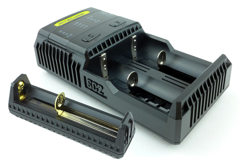
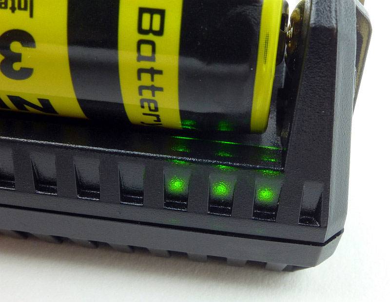
With so many chargers to choose from, it can be difficult to pick one, so you may be looking for those models with a little more to offer. NITECORE’s SC2 and F1 chargers both have extra features that make them stand out, so let’s see what they are.
A few more details of the F1:
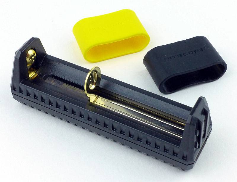
Starting with the smaller F1. Well ‘smaller’ doesn’t do it justice, this is tiny. I must also point out straight away, that this is not just a charger, but it is a powerbank as well. (NOTE: The F1 is only intended for charging Li-ion cells and needs a Li-ion for use as a USB powerbank.)

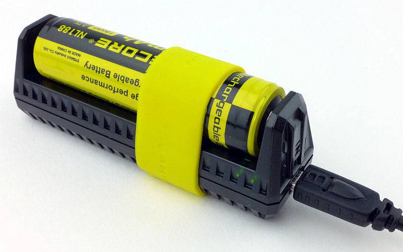
Along with the F1, you get two rubber bands which are used to secure an 18650 in the charging slot. This is for when you use the F1 as a powerbank and want the cell to stay in place when you carry it.
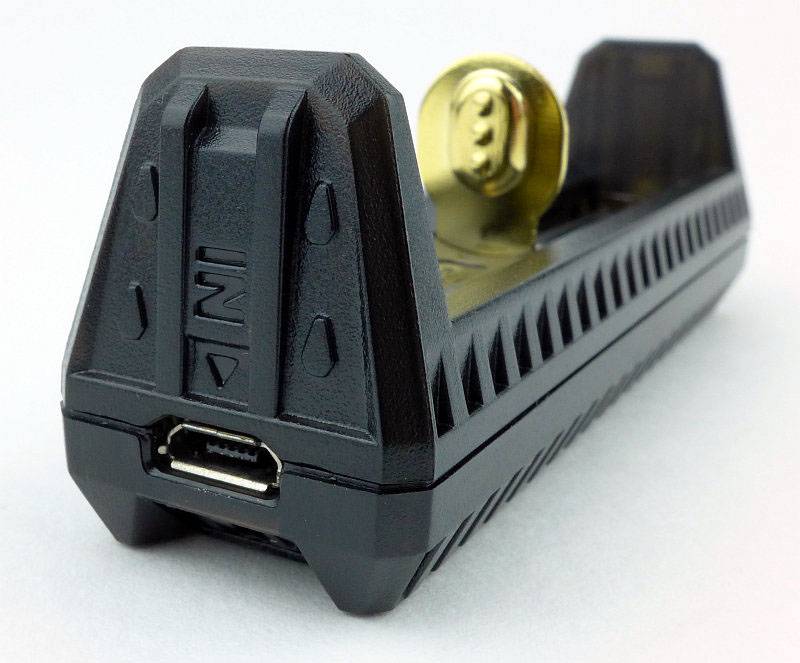
At one end of the F1 is a micro-USB socket which is used for the input power to charge the cell fitted into the F1.
Switching to the other end, the F1 has a full size USB socket which can provide USB power output up to 1000mA.
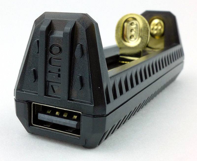
The F1 contacts are gold plated.
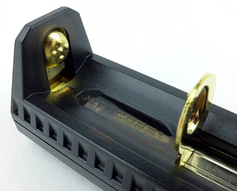
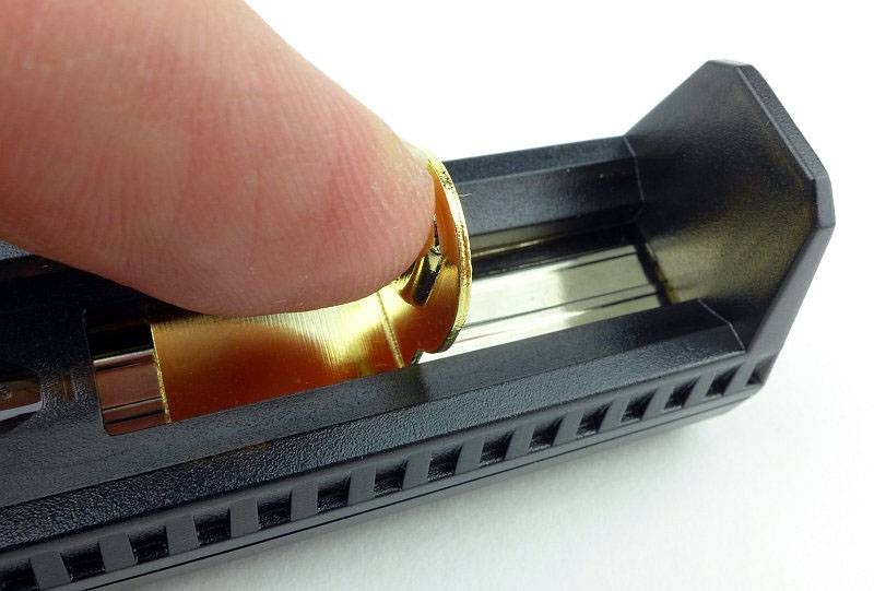
With a spring loaded sliding contact, the F1 can be used for any of the following Li-ion cells; 26650/18650/17670/18490/17500/17335/16340(RCR123)/14500/10440.
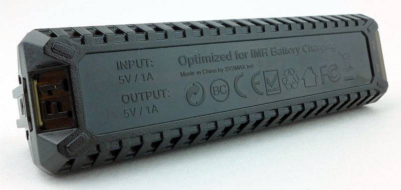
Underneath is basic information about the input/output ratings of this charger/powerbank.
A few more details of the SC2:
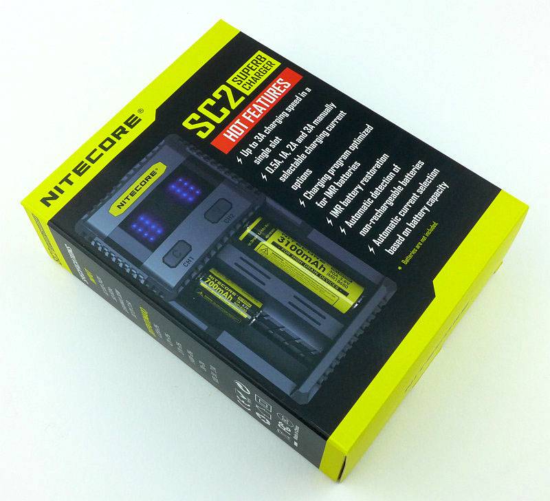
With the SC2 we have quite a step up in power, and one of the headline specifications is a 3A charge current (if using 3A in one slot the other can only provide 2A), ideal for IMR or high capacity cells. This charger is compatible with a huge list of cells including both Li-ion and Ni-Mh cells.
With the SC2 you get a suitable mains lead (in this case a UK plug) and the instructions. Don’t throw those instructions away, you will need them.
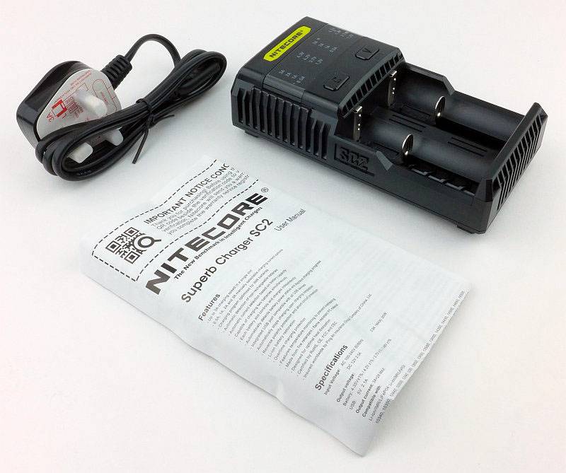
Relatively plain looking the SC2 is full of functionality.

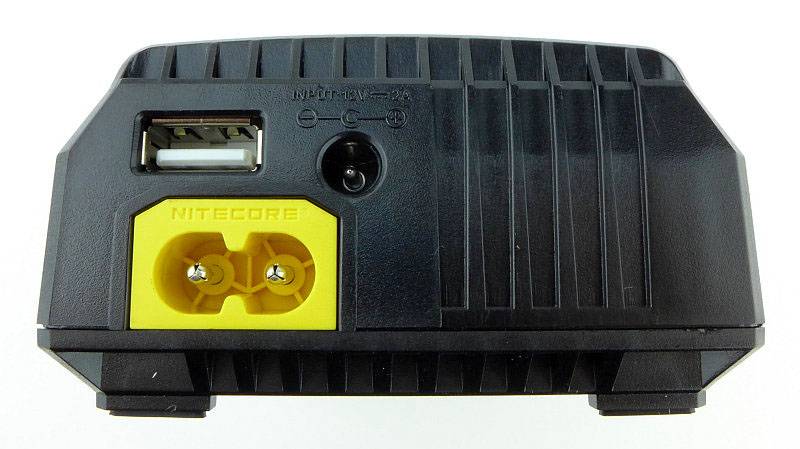
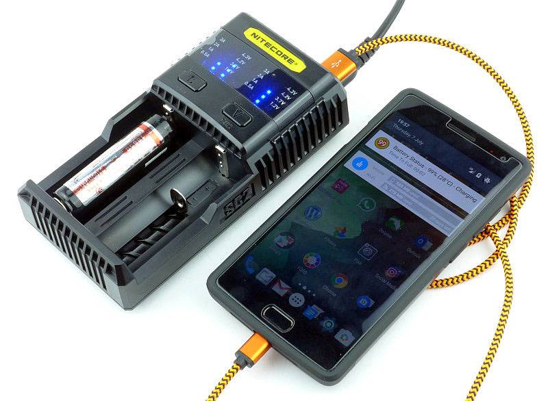
On the top end of the SC2 are the inputs and outputs. The yellow figure-8 socket is for the mains lead. There is also a 12V DC input for use in a car. Above the mains input is a full size USB socket which provides up to 2.1A USB charging output.
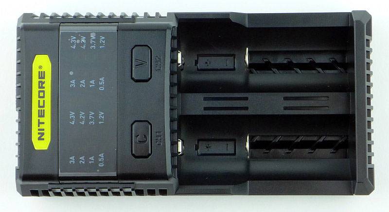
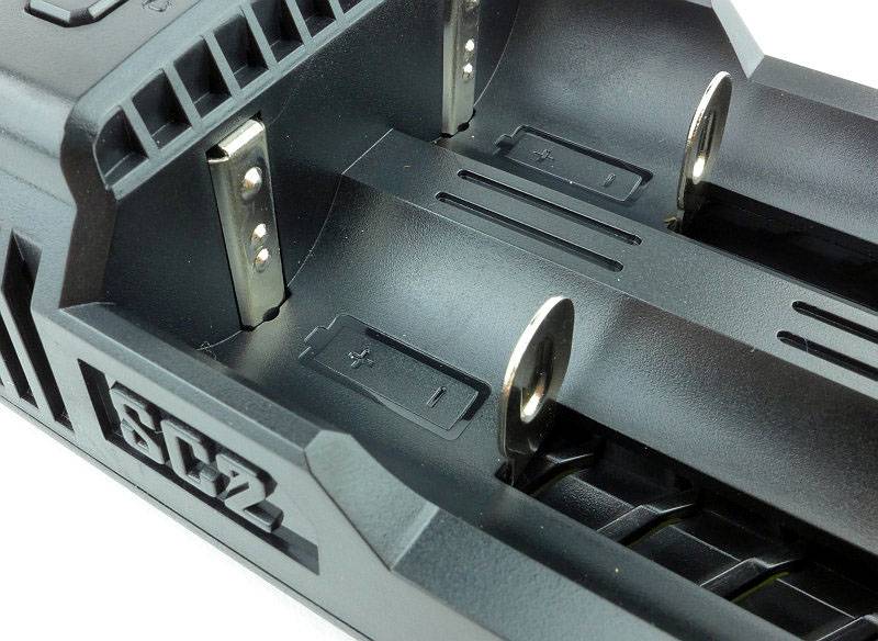
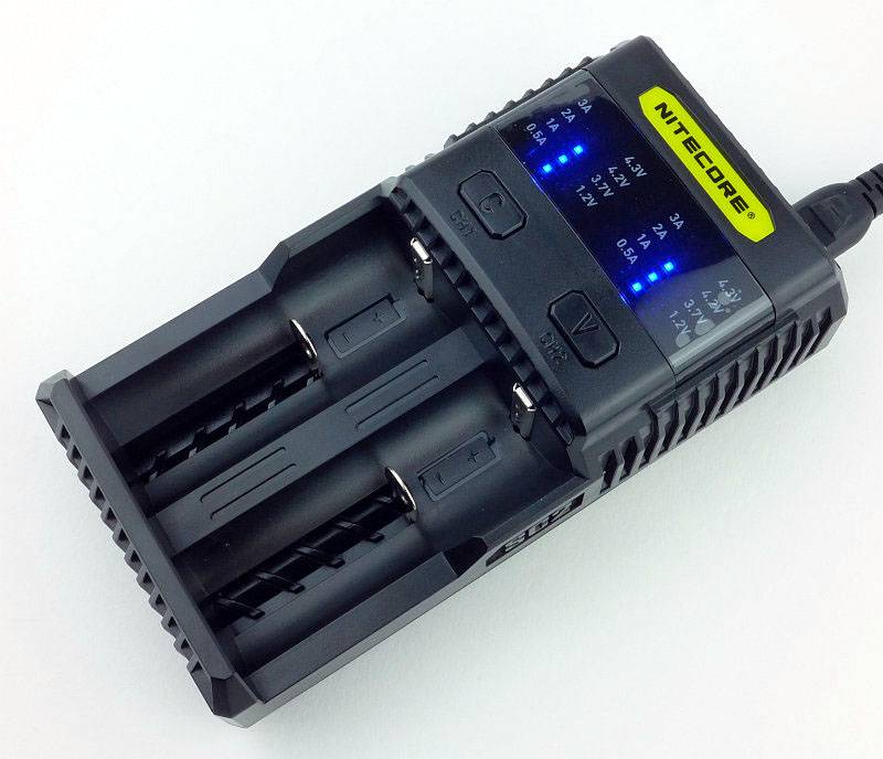
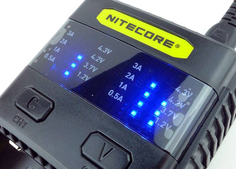
Considering its capabilities, the layout is very simple. There is an indicator panel (lights only, no digits are displayed), two control buttons, and the two slots.
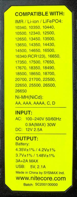
On the underneath there are four rubber feet and the list of supported cells.
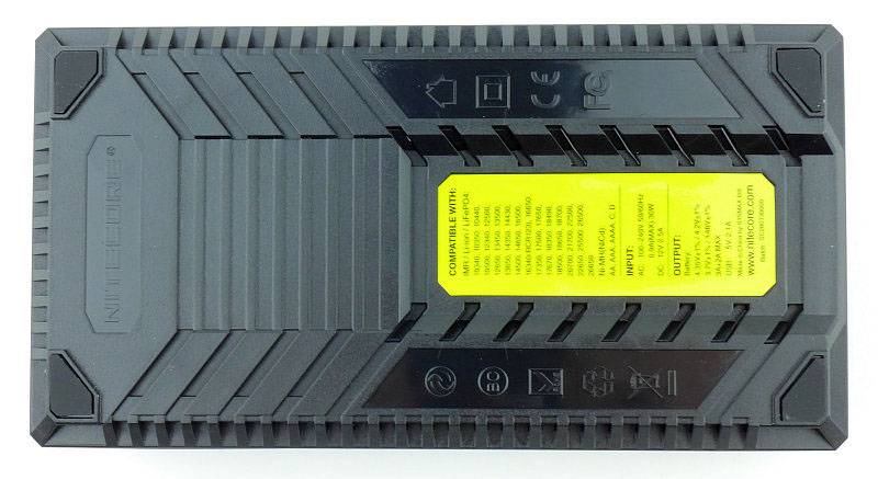
It’s a huge list of supported cells; IMR / Li-ion / LiFePO4: 10340, 10350, 10440, 10500, 12340, 12500, 12650, 13450, 13500, 13650, 14350, 14430, 14500, 14650, 16500, 16340(RCR123), 16650, 17350, 17500,17650, 17670, 18350, 18490, 18500, 18650, 18700, 20700, 21700, 22500, 22650, 25500, 26500, 26650
Ni-MH(NiCd): AA, AAA, AAAA, C, D
The contacts are the typical chrome plated type.
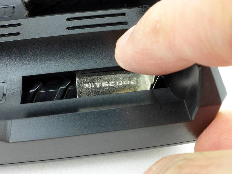
A nice detail is that the NITECORE name is stamped into the slider contact.
All the various options are selected using the two buttons. The C and V represent the Current and Voltage settings you can select.
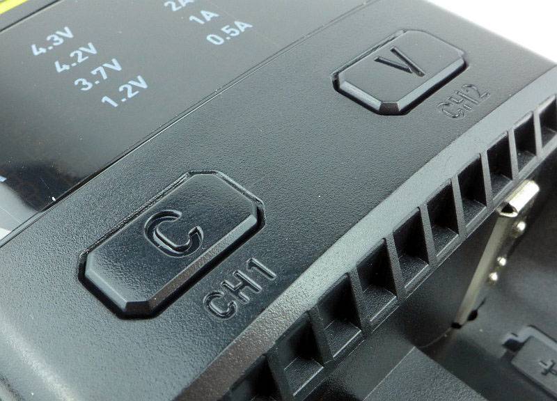
When first powered on, the SC2 shows a set of lights indicating the default of 2A charging current.
What are they like to use?
The F1 is one of those ‘don’t need to think about it, just buy it’ products for me. Combining the function of a Li-ion charger and powerbank into a tiny, easy to carry, device just makes it a must have EDC device.
When you insert a cell, it also tells you the voltage, so will work as a cell checker as well. If you use li-ions and have a smart phone, you will want one of these.
I’ve given the review sample a really hard time, with the worst conditions being the F1 having a 26650 fitted and used as a powerbank for a set of USB lights that try to draw 3A. Considering this should only output 1A, the actual output current was around 1.5A. Like this it was allowed to run constantly all day for a couple of weeks, swapping the 26650 when required. During this time the F1 did get hot, but expecting this to become a destructive test due to the extended abuse, I was impressed to find the F1 survived this without any issues.
For more details, have a look at the instructions by clicking on this image for the full size version. (Depending on your browser you might need to ‘right-click’ and ‘open in new tab/window’.)
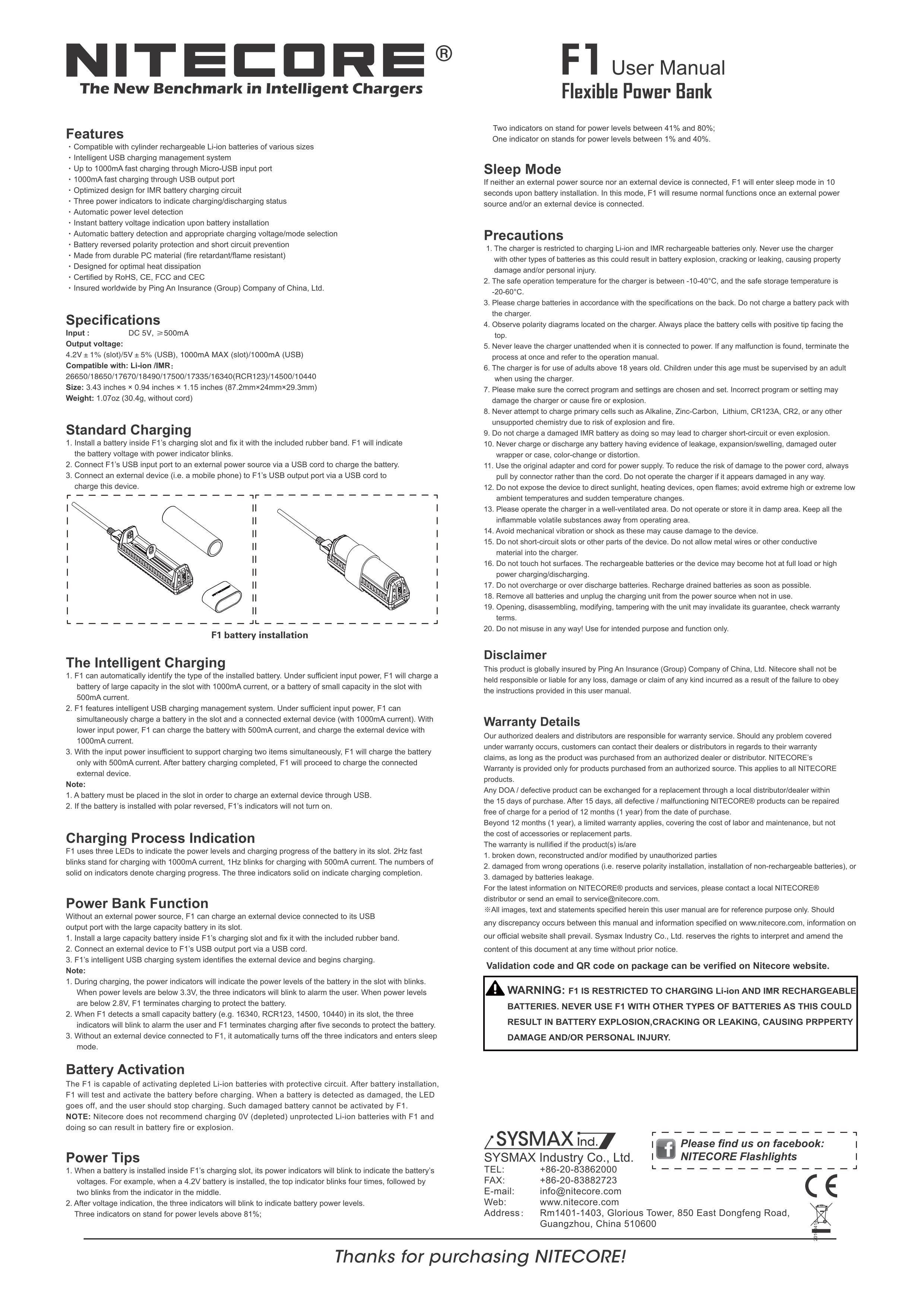
Hidden within the casing are three green indicator lights. These tell you the cell voltage when inserting a cell, the remaining capacity when using as a powerbank, or the charging status when charging a cell.
The ideal cell for powerbank use is an 18650, and the supplied rubber bands fit this size cell perfectly. This is how it looks when you have it ready to carry as a powerbank.
It is important to note that there is parasitic drain when in Powerbank configuration which in the sleep/low power mode measures at 390uA. When using a 3100mAh cell it will take 331 days to drain the cell.
According to the YZX Studio Power Monitor, the output of the USB charging port is ‘Android DCP 1.5A’ meaning the D+ and D- lines are shorted.

Once you are back at home/work, just top up the cell with any USB charging point. Of course another major advantage of the F1 as a powerbank is that you can carry spare cells for it, and swap as needed.
Now onto the SC2. This is a very versatile charger, but I have to say it has not been the easiest to work with. Using the defaults is easy. Turn it on, and pop in your cells, the SC2 will charge them quickly, but it is when you want to change modes that it hasn’t been that easy. Because of this I’m not even going to attempt to explain so you definitely will want to refer to these instructions. I did find that some double clicking was required to enter manual mode. This is not mentioned in the instructions, so if it is not responding as you expect, try a double click.
Click on this image for the full size version. (Depending on your browser you might need to ‘right-click’ and ‘open in new tab/window’.)
Here is an IMR cell (from the TM03) charging on defaults. It is now displaying a full charge, as during charging the current lights show the charging current, and the voltage lights are used to display charging status with three LEDs. Once the three LEDs remain on steady, the cell is fully charged.
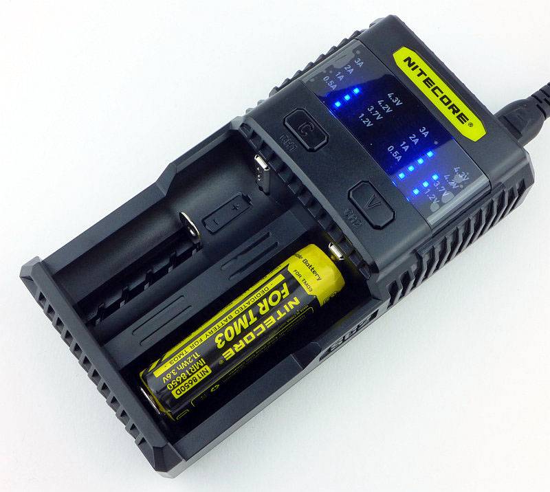
It is important to note that due to the high charging current, the SC2 will terminate a little early. You don’t quite get a completely full charge. You can always pop the mostly full cell into another charger for that final top-up but you don’t really need to.
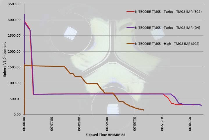
This graph has three traces on it and two of them compare the SC2 and D4 chargers (both used to charge the TM03s’s cell).
The SC2’s slightly early termination can be seen with the earlier drop to low mode at around 1h 20m. Considering the vast reduction in charging time, this minor loss in overall output is well worth it.
There is one major design flaw with the SC2 sent to me. The numbers on the display to show current and voltage are only printed on the plastic film on the display. When you unpack the charger you normally expect to remove a protective film from the display. As you do this, you find the numbers come off as well!
I had to put the film back on after finding this which is why there are some bubbles under the film.
My advice is to NOT remove the protective film (unless you have confirmed the number are now printed on the actual display.
As explained in the user manual, Slot 2 and the USB charging output contend with each other. If the cell in Slot 2 is charging the USB output is stopped. So you can charge a cell in Slot 1 and a USB device at the same time, but if using Slot 2, only once the cell is charged does the USB charging work.
Review Summary
The views expressed in this summary table are from the point of view of the reviewer’s personal use. I am not a member of the armed forces and cannot comment on its use beyond a cutting tool or field/hunting knife.
Something that might be a ‘pro’ for one user can be a ‘con’ for another, so the comments are categorised based on my requirements. You should consider all points and if they could be beneficial to you.
| _______________________________________________ | _______________________________________________ |
| Things I like | What doesn’t work so well for me |
| _______________________________________________ | _______________________________________________ |
| F1 – Tiny Li-Ion Charger. | F1 – Parasitic drain could be lower. |
| F1 – Tiny Powerbank with changeable cell. | F1 – Cell quite easily knocked even with rubber band. |
| F1 – charges from any micro-USB charger. | |
| SC2 – Super Fast 3A Charger. | SC2 – Display Labels Printed on removable protective film. |
| SC2 – USB charger output. | SC2 – Mode changing a bit tricky. |
| SC2 – Huge list of compatible cells. | SC2 – Cells not quite fully charged. |
| SC2 – Mains and 12V power options. |
Discussing the Review:
Please feel free to add comments to the review, but the ideal place to freely discuss these reviews is on a forum. If you started reading the shorter forum version of the review, but followed the link this full exclusive review, please return to that forum to discuss the review there.
If you read the review entirely on Tactical Reviews, please consider one of the following to join in any discussion.
EdgeMatters – Sponsored Reviews (UK based Forum for Knife Makers and Collectors)
CandlePowerForums – Knife Reviews Section (Largest and Friendliest Flashlight Community Forum)