Gear Review: FLIR Scout TK Thermal Camera

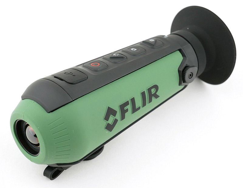
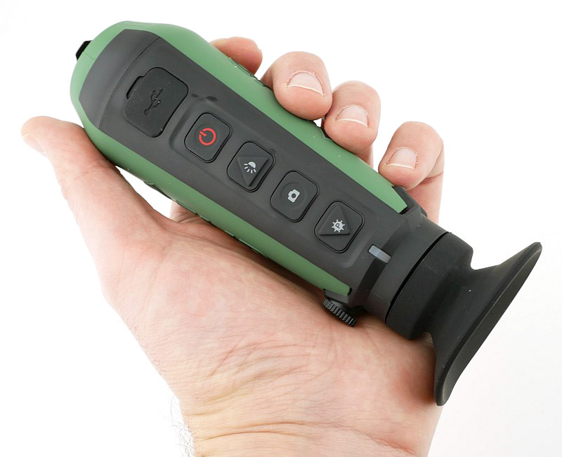
FLIR are a leading manufacturer of thermal imaging sensors and thermal cameras, and though this technology still remains relatively expensive, FLIR have been producing consumer devices that bring thermal imaging within reach for everyone. In this review we are looking at the Scout TK, FLIR’s palm-sized self-contained thermal vision monocular, which reveals details of your soundings and helps you see people, objects and animals up to 100 yards away.

A few details:

When working out the best order for the content in this review, I’ve settled on a good look around the Scout TK before diving into the how and what of thermal cameras. So here we go with the details of this handy scope style camera.

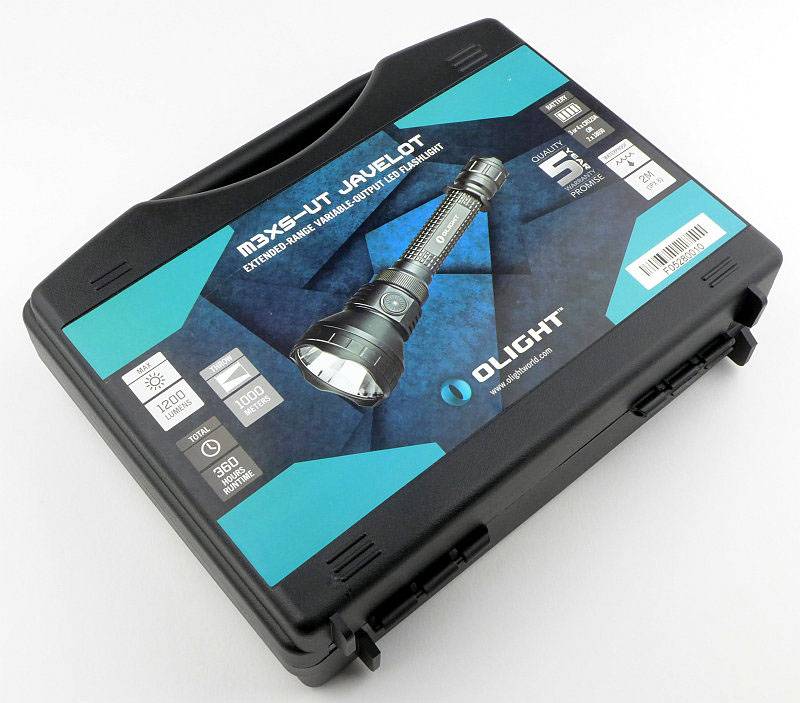
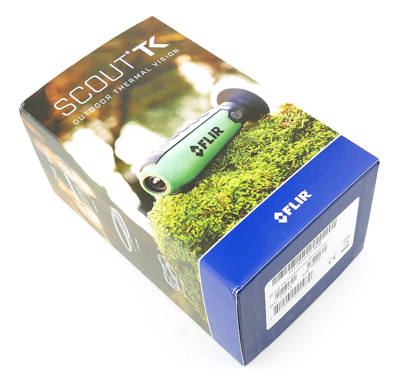
You are greeted by a well presented box with over-sleeve.

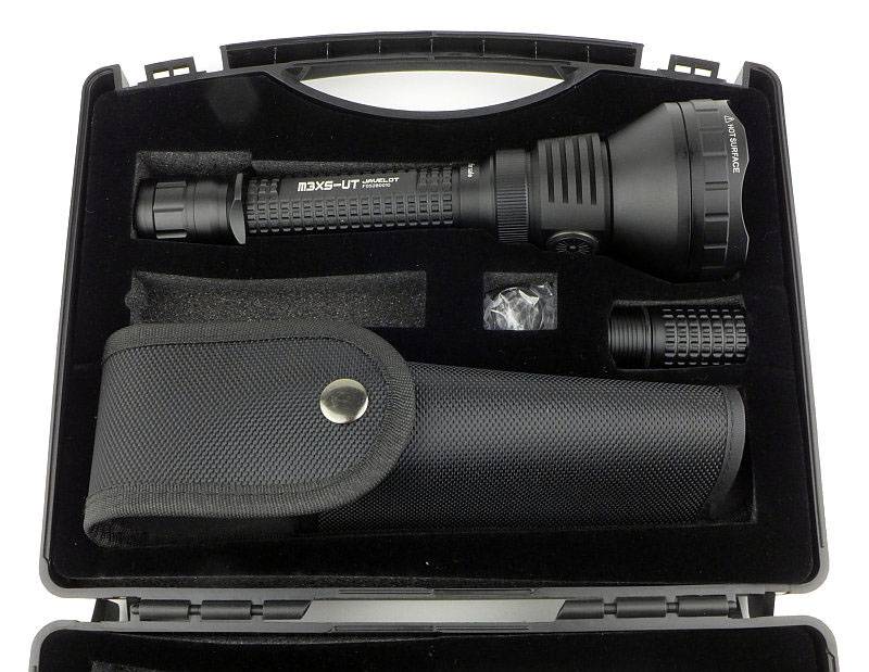
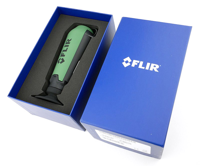
With the sleeve off the main box, we can lift off the lid. The Scout TK is well protected by a closed cell foam liner.

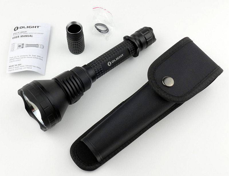
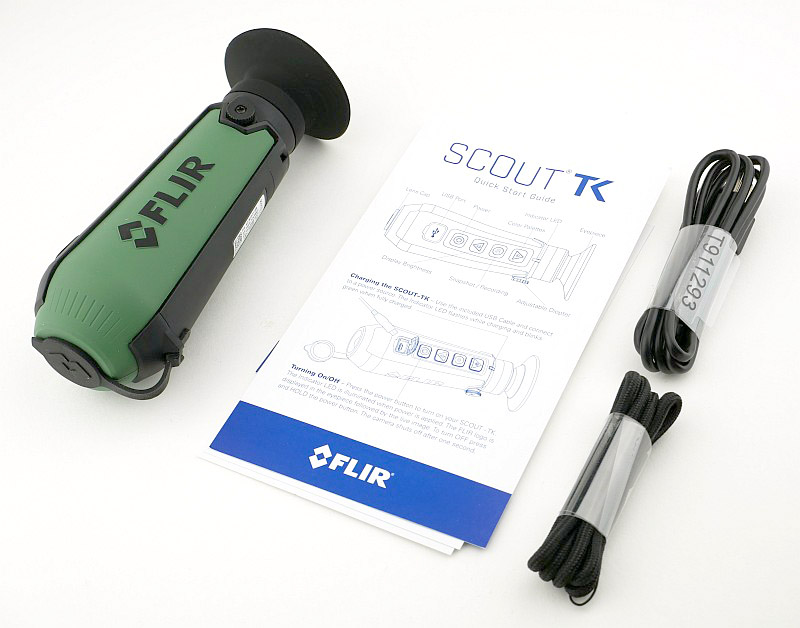
In the box is the Scout TK, a neck lanyard, a USB cable and the instructions.

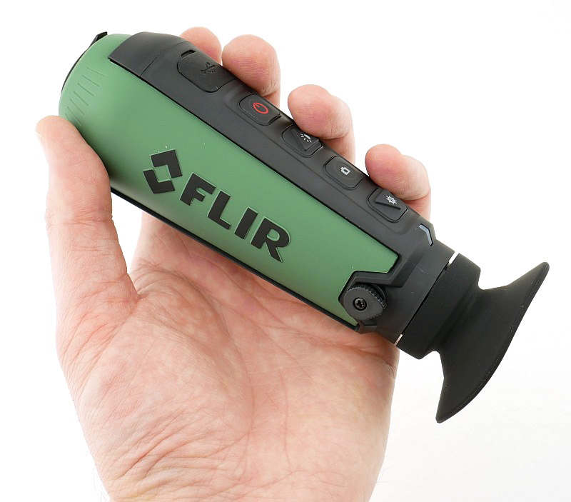
A very neat and purposeful design.

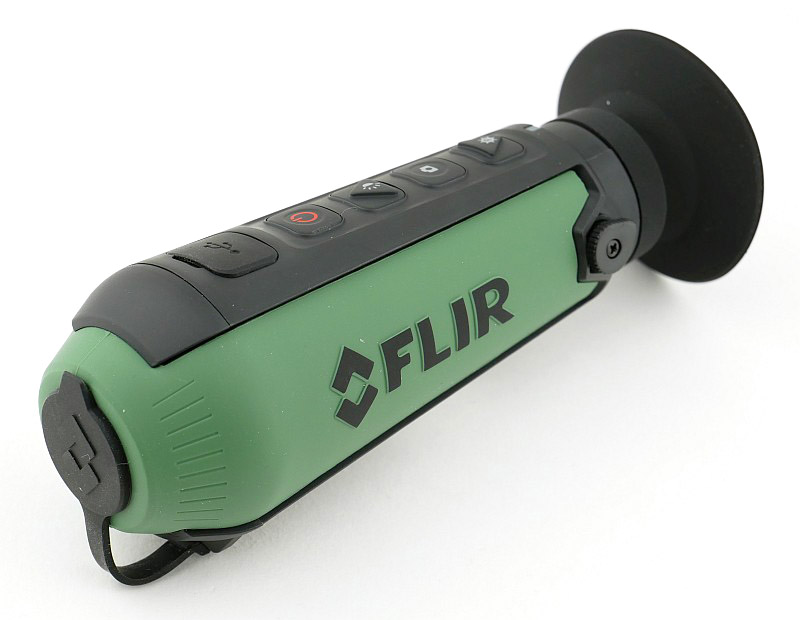
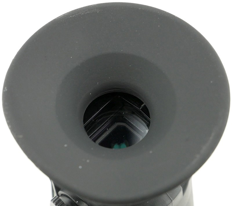
Protecting the Scout TK’s ‘eye’ is a rubber lens cover.

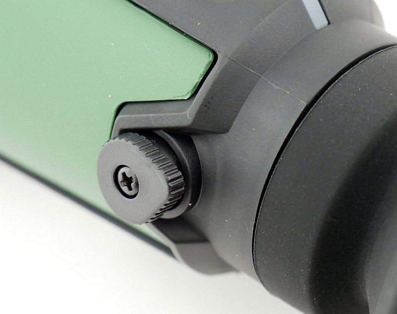
On the left side of the eyepiece is a diopter adjustment, to allow the user to focus the view of the internal display.

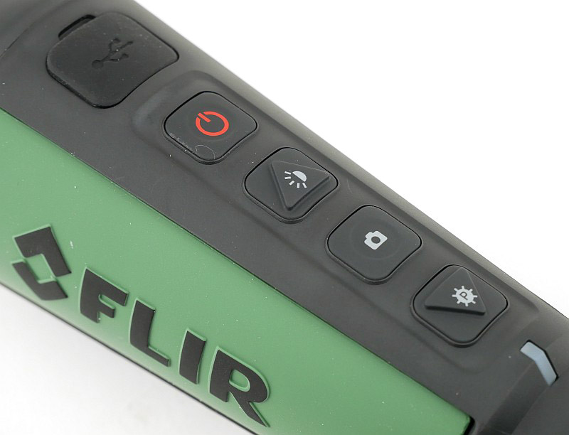
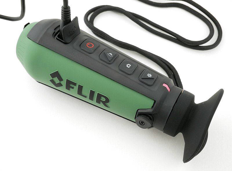
The top of the Scout TK has a set of four control buttons, plus the USB port cover. The buttons are basically Power, Brightness, Shutter and Palette.

There is a wide, soft, eyecup shield to keep light in/out.

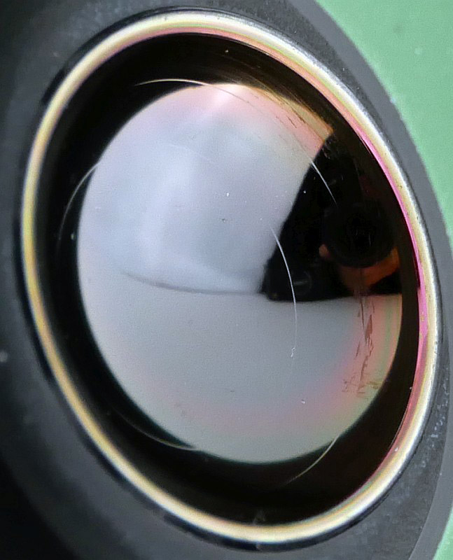
With the lens cover off we can start to see the odd looking thermal camera lens.

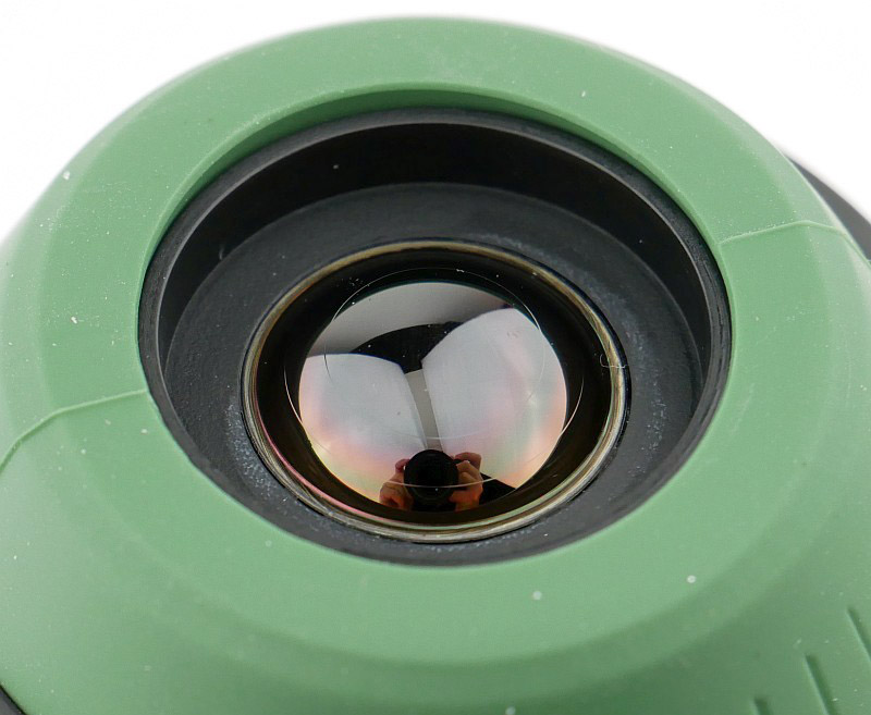
Materials and construction of the thermal camera lens are specialised as it is focusing infrared, not visible light.

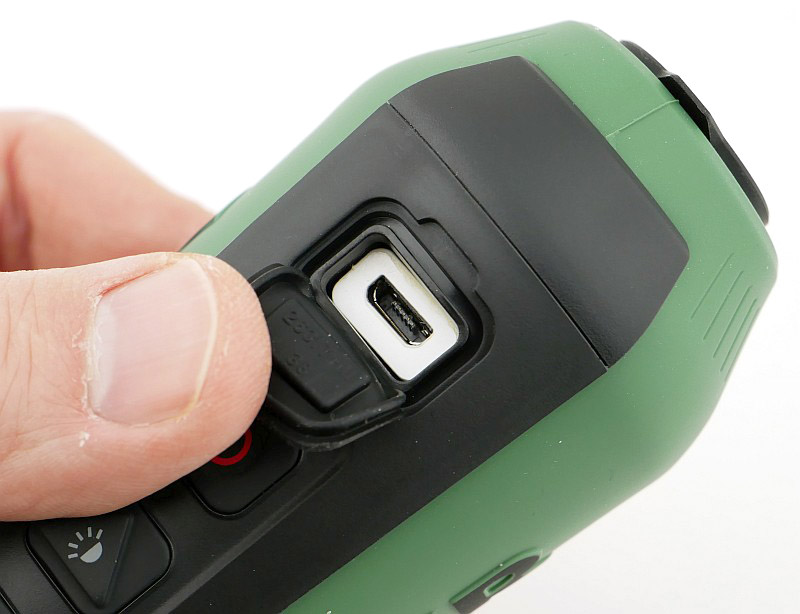
Pulling back the rubber USB port cover gives access to the micro USB port which is used for charging the internal battery and downloading the photos and video.

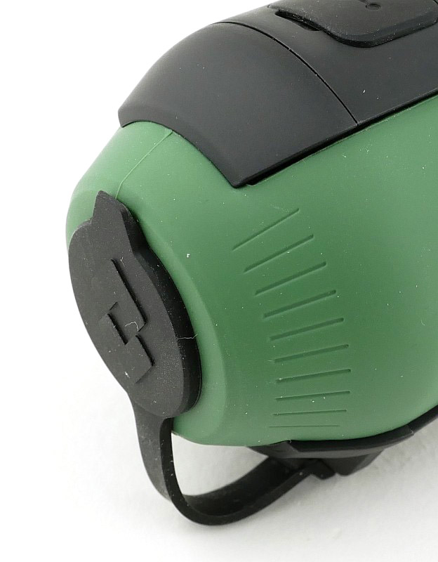
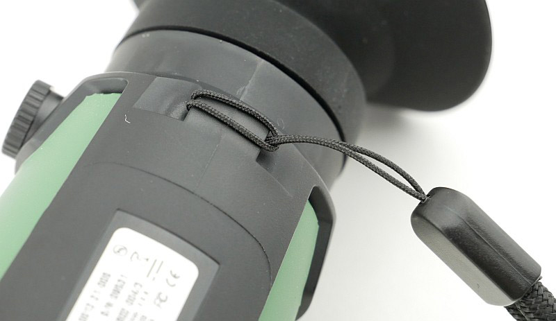
Though is it low-profile, the lanyard hole is easy to use.

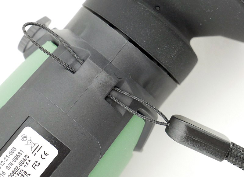
Being a reasonable investment, it is a good idea to use the lanyard.

Plug in the supplied USB cable for charging and/or data transfer. This has a relatively slim plug, and some other cables don’t fit properly into the port.

Before using for the first time I gave it a full charge.

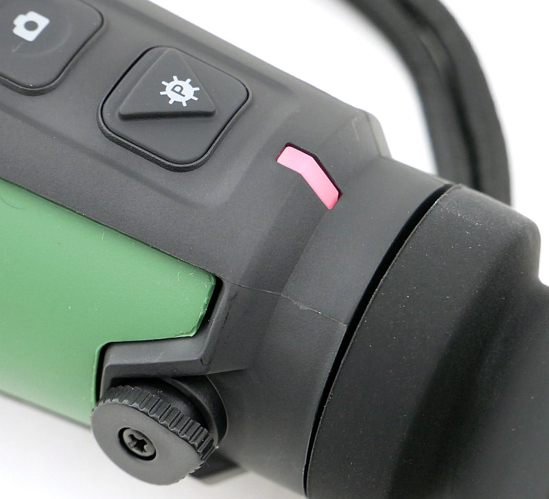
During charging the indicator light flashes red. This turns green once the battery is full, but keeps flashing.

A little Theory (read at your own risk):

If you just want to get on and see more of the photos and video the Scout TK can give you, then feel free to skip over this section, but if you would like to know a little more about how and what it is really doing, then hopefully this section will help illuminate you, and with this knowledge, you can better understand how best to use it.

What is this camera actually seeing? Just as our eyes respond to visible light (which is a small range of wavelengths of Electromagnetic Radiation on the Electromagnetic Spectrum), the sensor in the Scout TK responds to a different range of wavelengths that our eyes cannot see.

Electromagnetic Radiation is typically referred to by its frequency or wavelength, and we are going to use the wavelength to quantify where we are on the Electromagnetic Spectrum. For those not familiar with the concept, just think of waves in the sea, and how far apart the crest of each wave is from the previous wave (wavelength). Waves that are closer together have more energy, and waves that are further apart have less, of course the wavelengths we are looking at here are tiny compared to waves in the sea.

A typical human eye will respond to wavelengths from about 390-700 nm (that is 0.00039-0.0007 mm). The Scout TK uses a ‘FLIR Lepton sensor’ which responds to wavelengths between 7500-13500 nm – referred to as long-wavelength infrared.

Hopefully you are still with me as this is where is gets interesting.

The reason the sensor in the Scout TK has been made to respond to this range of wavelengths is because this is the ‘thermal imaging’ region of the Electromagnetic Spectrum. Objects at temperatures between -80 °C and 89 °C, purely due to their thermal energy (temperature), emit electromagnetic radiation in this band of wavelengths. As the objects themselves are emitting the radiation, there is no need for any ‘illuminator’ or external source of light. The objects simply ‘glow’, in infrared, all by themselves, and the camera sees their emissions directly.

This is a completely passive observation of the objects, needing no visible light or any other source of illumination, but it does bring us to one more important aspect of this to understand.

Because we are passively observing the radiation emitted by the objects themselves, and the wavelength of the infrared radiation ‘seen’ by the camera sensor depends on the temperature of the objects, we are really only ‘seeing’ temperature differences. If everything observed by the camera is actually the same temperature, it isn’t possible to distinguish any of the objects – they all just appear the same shade of grey. So what we want (and need) is temperature difference to be able to ‘see’ with a thermal camera. This concept will become clearer during the review when we look at what you need to bear in mind to get the best out of it.

Now that I’ve brought up the requirement for there to be a temperature difference to be able to ‘see’ anything with the thermal camera, to understand some of the images shown in the review, it is also necessary to understand how FLIR presents the observed picture. The sensor itself is capable of a ‘seeing’ very wide range of temperatures (-80 °C to 89 °C), but if this entire range was used all the time, you would not see the difference of only a few degrees clearly at all. To get round this, constantly during use, the processor in the Scout TK takes the highest and lowest observed temperature values and sets these as the maximum and minimum temperature colours for the palette being used. (The palette is a range of 256 colours used to represent the different temperatures ‘seen’ by the camera sensor.) So, as soon as a much colder, or hotter, object comes into view, those maximum and minimum values shift, and smaller temperature differences lose definition.

Staying in the technical frame of mind, here are a few key features of the Scout TK:

Detector Type – 160 x 120 VOx Lepton ® Microbolometer
Thermal Sensitivity – Waveband 7.5-13.5µm
Field of View (H x V) – 20° x 16°
Media Storage – 1000 images and 4 hours of video
Eyepiece display – 640 x 480 pixel LCD
Refresh Rate – <9Hz Battery Type - Internal Li-Ion Cell Ingress Protection Rating - IP-67, Submersible

What it is like to use?

Hopefully you survived the thermal camera theory, as it helps explain some of what we see in this section.

Although the Scout TK might be the lowest specification of FLIR’s thermal camera scopes, it is also the most convenient to carry. The sort of thing you will take on the off-chance instead of specifically planning to need it.

Small enough to pop in a jacket pocket, or use the neck lanyard to carry around.

Getting started with the Scout TK and power it up with a brief press of the power button. About 10 seconds later the thermal imaging is shown on the internal 640 x 480 pixel eyepiece LCD.

During the startup, you might notice it clicking, and this also happens from time to time as you use it. While it is clicking the image being displayed freezes. This is a calibration process known as flat-field correction or FFC, and an integrated shutter performs the FFC automatically. Due to the nature of the sensor, and the fact it is ‘seeing’ infrared, which it itself is emitting, this calibration ensures that each pixel in the sensor is set to the same level when shown a uniform target (the shutter) ensuring there is no distortion of the thermal image.

So far, apart from when turning it on, I’ve not found a clear pattern of when the calibration triggers, but you will see it from time to time during use.

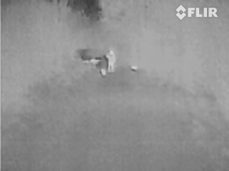
OK, so most importantly, what do we see? Well there is a lot more, but turn it on out of the box, and this is the sort of thing you immediately have revealed. Here, down a dark unlit path is a dog-walker and two small dogs.

With the Scout TK using an eyepiece display, the brightness of this could be too dim for daylight use, or too bright for dark adapted eyes, but of course, FLIR have included brightness adjustment. You’ll find out how important this is the first time you let your eyes adjust to the dark. Fortunately it is quick and easy to dim the display to a comfortable level. Thanks to the eye shield, I’ve actually found the dimmed display fine for daytime use as well.

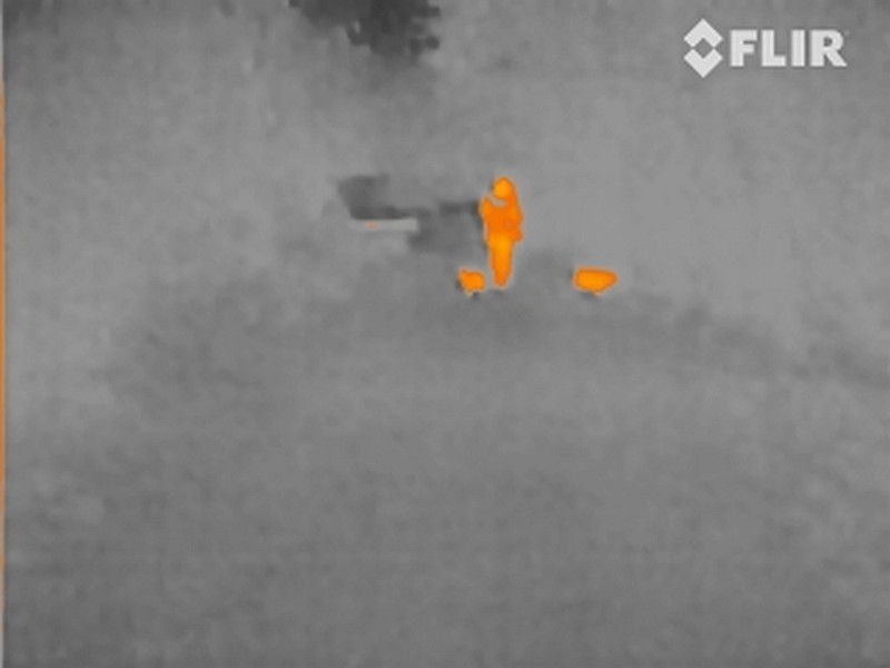
The previous image was pretty clear anyway, but change to a different palette (more on those in a minute) and they definitely stand out now.

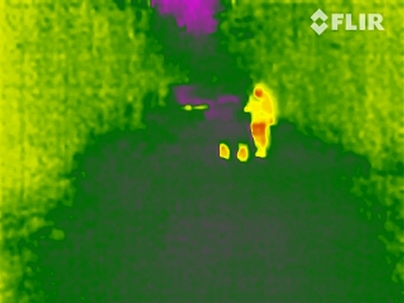
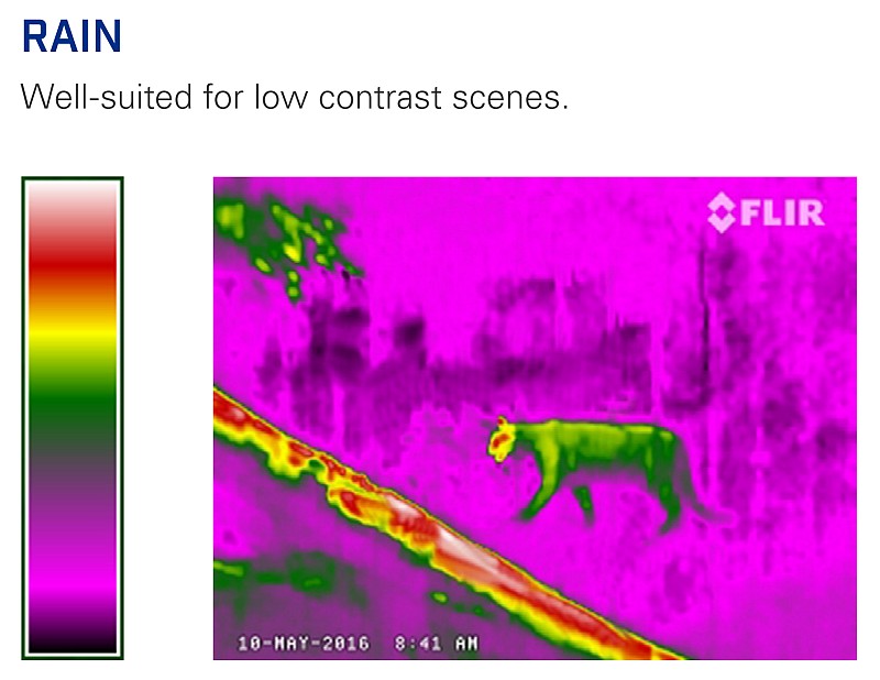
The same scene again, but using the palette which has become the most useful to me, called ‘Rain’, and there is no mistaking our dog-walker.

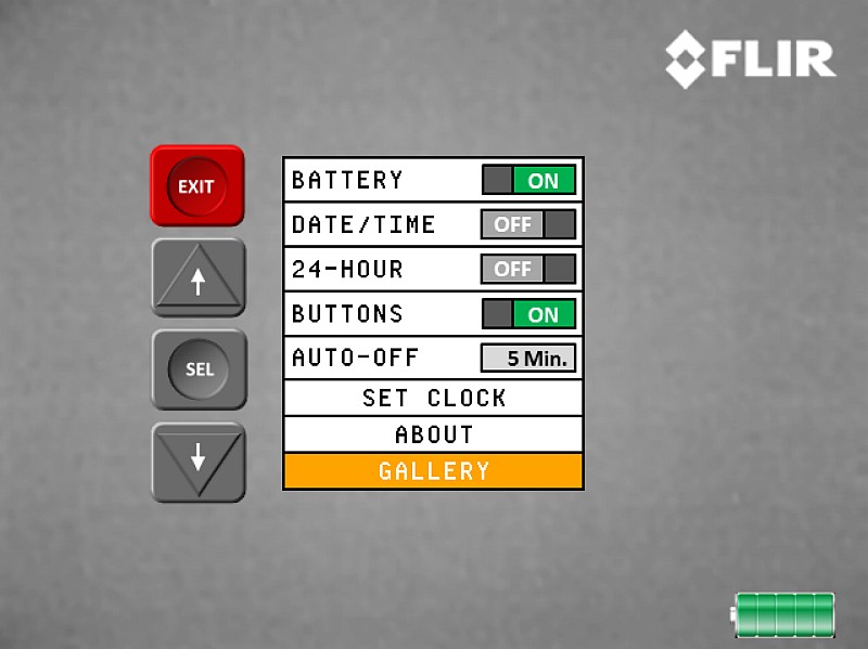
We’ll cover the most important feature of palettes in more detail, but before moving on, there is a simple menu system for the few settings you might want to tweak from their defaults. Through this menu you set the date/time and tweak what is displayed. You can also enter the basic Gallery to view photos you have taken (videos don’t play back).

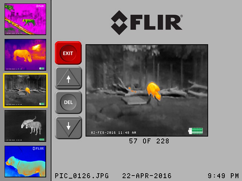
Opening the Gallery means you can browse through the images. They are shown quite small with there being no full screen view, only what you see here. Videos are shown as a still image, but won’t play.

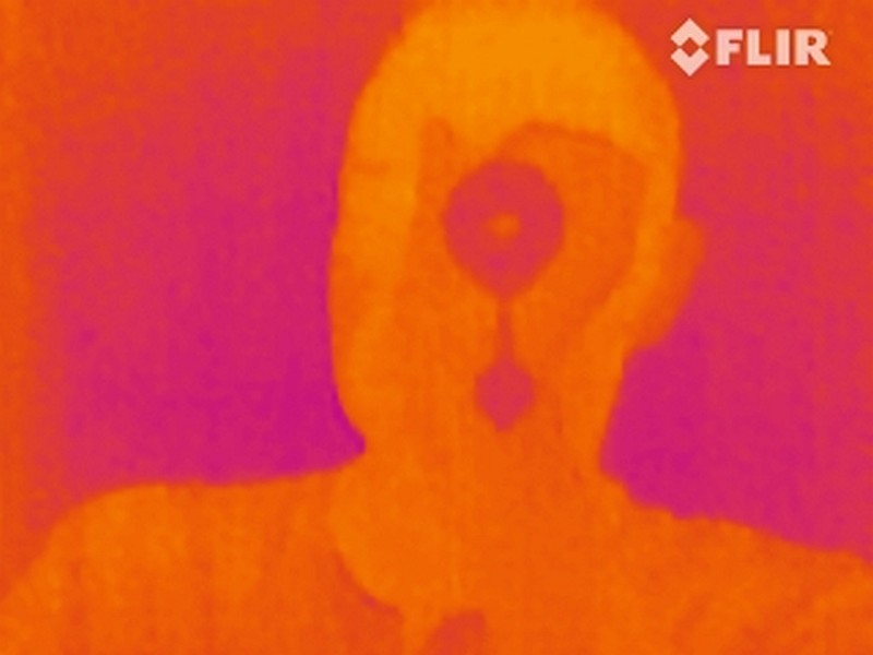
It might not be your first question, but it was one of the things I tried straight away, ‘can it be used through glass?’; this is your answer. Of course modern glasses are specifically designed to keep heat in, including infrared, so it is basically an infrared mirror.

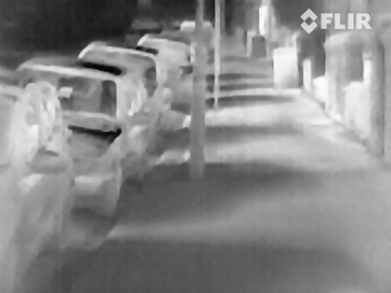
Designed with the outdoor enthusiast in mind, in the urban environment there are still many things you might use this Scout TK for, including finding overheating appliances, missing home insulation, and this list just goes on and on. In this case I wanted to know which car was the one that had just parked. No question there.

Part of the reason for all the theory included earlier is to understand one possible issue you may encounter in certain situations.
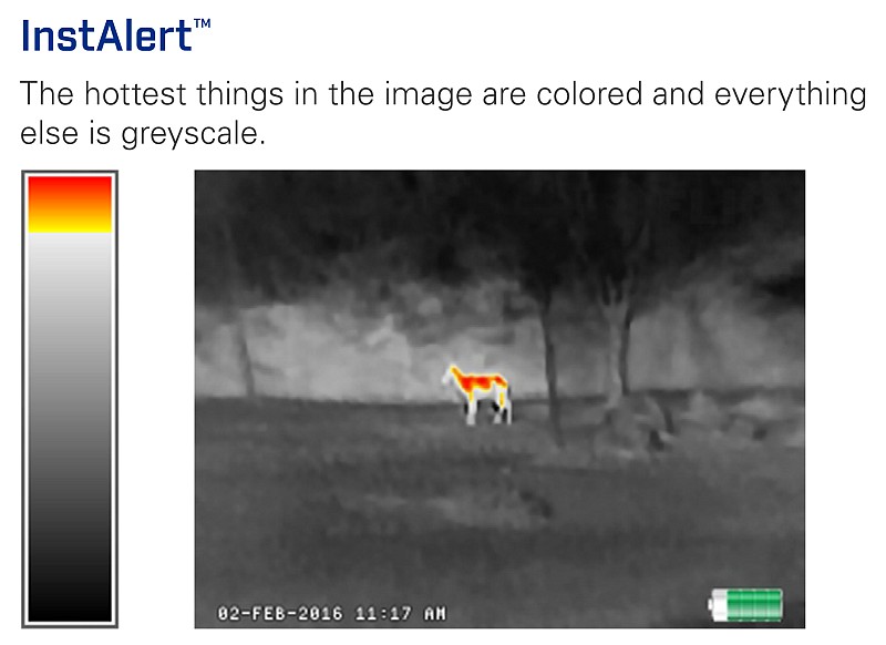
This scene is of a path through open countryside. At the very top, you see just a hint of sky (black). The Scout TK is set to use the Instalert palette to hopefully make it easy to spot any animals.

Lifting the view just a little brings more of the sky into view, and suddenly all of the bushes and grass are on fire! Not terribly useful.

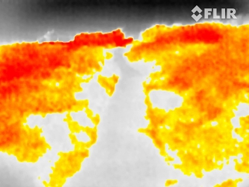
OK, so what happened? It comes down to the way the camera calculates the colours to match the current observed temperature profiles. Moving the camera so you now include the sky in the image means this becomes the coldest thing; there are now fewer colour variations available to show differences in temperature between a bush and an animal. Once you understand this you can avoid washouts like this; to get the best colour contrast, avoid getting extreme temperatures into the image (sky/ice etc).

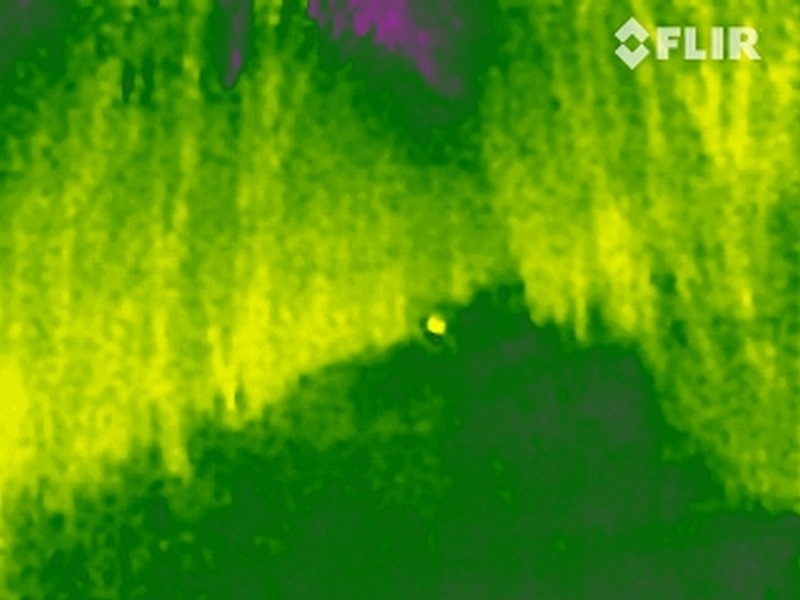
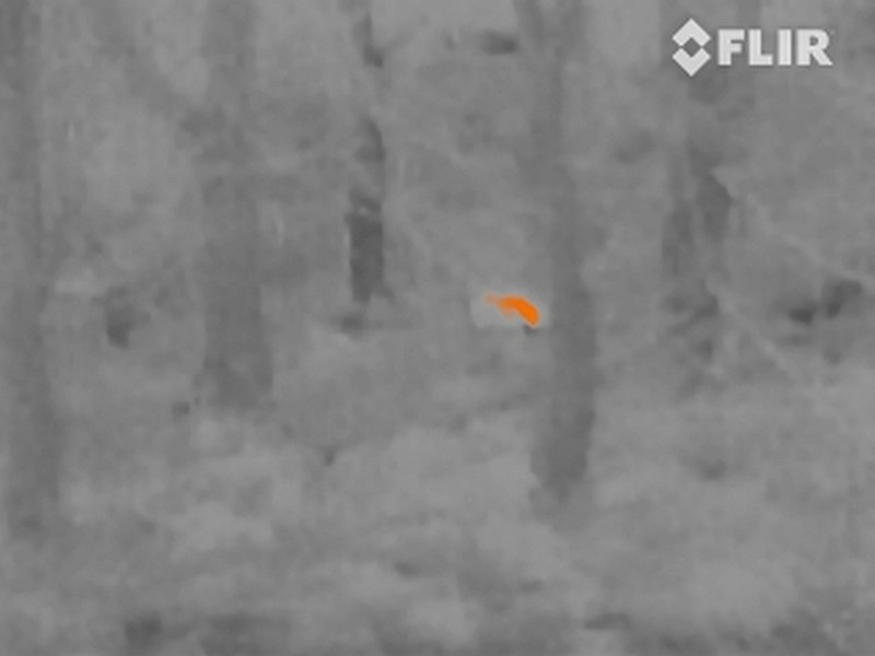
The term palette has come up several times and these are one of the most useful settings in a thermal camera as each has a particular benefit. One of my most used palettes is ‘Rain’ which works for low contrast scenes. Here a fox is clearly visible in the distance when the other palettes barely showed anything.

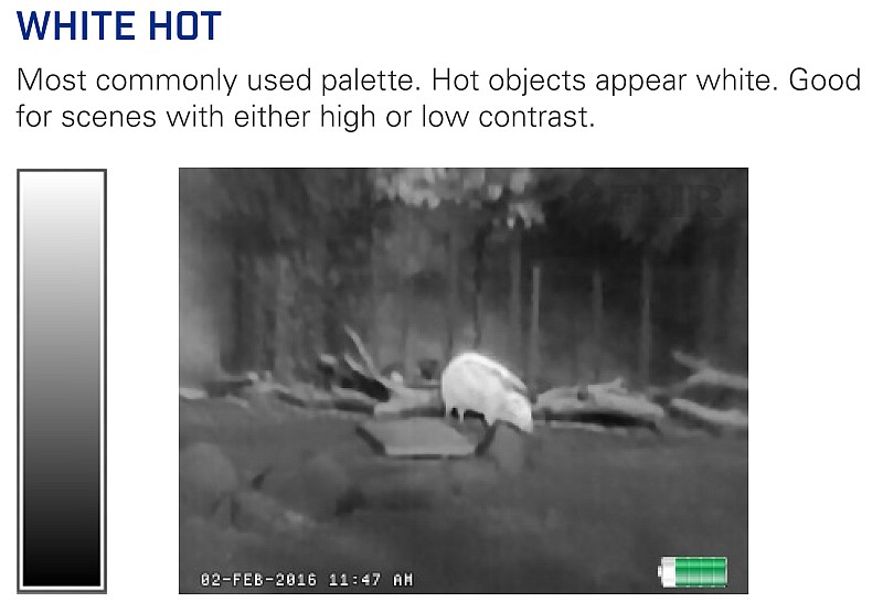
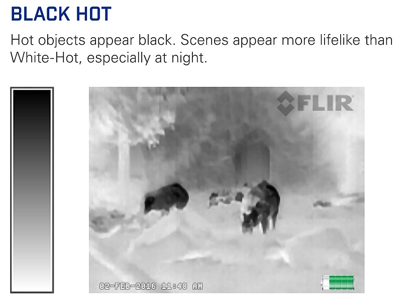
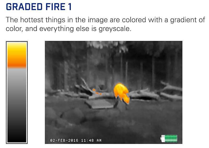
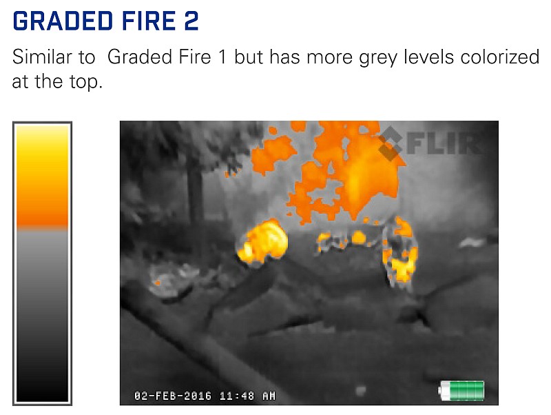
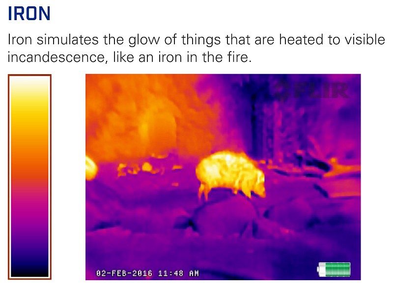
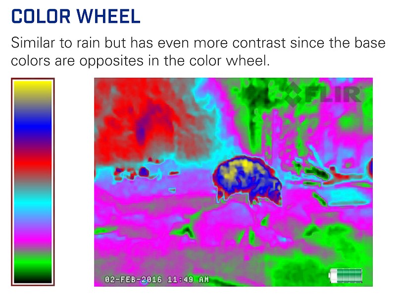
Taking these images directly from the Scout TK documentation, this is the full set of palettes you can choose from.

Palettes:

What we have seen so far are still images such as this one of a ……… Oh, yes this not much help, is it, as a still image? Unfortunately this particular sighting did not get captured as a video, and what was clear from the moving image in the eyepiece was that this is a badger.

So, lets have a look at some video from the Scout TK and you’ll get a much better idea of what it is like to use.

Video Edited with – Cyberlink Director Suite 5 (PowerDirector 16 and AudioDirector 7)

In real terms, you will be making your observations live with the Scout TK, but if you want to capture those observations to share, taking still images is good, but taking video even better.

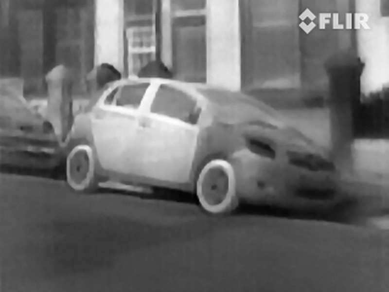
What about the daytime? A thermal camera is going to work best when there are the greatest differences in temperatures, and it is at night when the animals you are looking for will stand out against a cool background. However, it can be quite interesting to use a thermal camera in daylight and you see things quite differently.

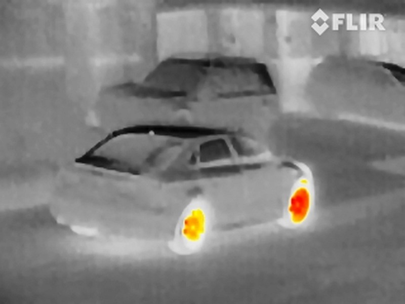
At first this image looks almost as you might expect for a black and white visible-light image. The shadows from the cars that are cast onto the pavement, are not exactly that. They are the shadows of the cars, but here we see them as colder areas as the sunlight is not warming the ground. We see the lack of warmth, not the lack of light.

This patchy looking car doesn’t have a funky paint job and white wall tyres, it is actually silver with plain black tyres. What we see is how the sunlight is heating up different parts of the car. The black rubber tyres are soaking up the heat of the sun and get nice and warm. The doors are insulated and so heat up more than the rest of the body, and the plastic bumper is also heating up differently.
Direct sunlight, and the heat it imparts to what you are observing, either conceals or reveals details, so is interesting but a bit hit or miss.

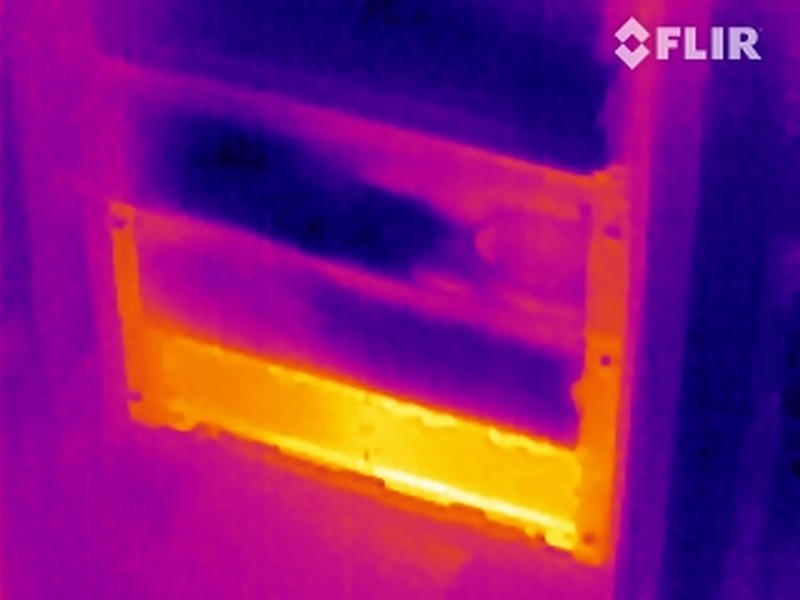
As portable as the Scout TK is, I wouldn’t normally carry it as an EDC, so it was just luck that meant I had it with me when a burning smell was reported coming from the server room at the office. With no obvious smoking or dead equipment, a quick scan with the Scout TK identified the culprit in less than 30s.
The lower battery bank of a UPS was significantly hot on one side and heating the battery bank above it. All healthy UPS units were cold, but not this one.

After electrically isolating the lower battery bank so it was no longer powered, a couple of hours later the two healthy UPS components were cold again with only the problem battery bank showing residual heat. After removing the four battery trays in this bank, the two on the right where the heat was seen had swollen and melted batteries with acid leaking. Thanks to the Scout TK the problem was found and dealt with very quickly.

With the design of the Scout TK, FLIR have kept is simple and fully self contained. This makes it easy to carry and easy to use. Compared to some of the more advanced cameras (and significantly more expensive), the Scout TK has a few limitations, but these are intentional and allow the Scout TK to be easy for anyone to pick up and use. Once you have your preferred palette and display brightness selected, the Scout TK can actually be a single button device – the power button – turn on, observe, turn off.

Review Summary

The views expressed in this summary table are from the point of view of the reviewer’s personal use. I am not a member of the armed forces and cannot comment on its use beyond a cutting tool or field/hunting knife.

Something that might be a ‘pro’ for one user can be a ‘con’ for another, so the comments are categorised based on my requirements. You should consider all points and if they could be beneficial to you.

_______________________________________________ _______________________________________________
Things I like What doesn’t work so well for me
_______________________________________________ _______________________________________________
Self-contained thermal camera. Thermal technology is still expensive (£500-£577).
Scope style body for intuitive use. Gallery display is small and does not play back video.
Wide range of useful palettes. USB data transfer seems to be USB 1.0 speed.
Excellent battery life.
Records images and video.
Robust, easy to use design.


Discussing the Review:

The ideal place to discuss this reviews is on a forum. If you started reading the shorter forum version of the review, but followed the link this full exclusive review, please return to that forum to discuss the review there.
If you read the review entirely on Tactical Reviews, please consider one of the following to join in any discussion.

CandlePowerForums – Knife Reviews Section (Largest and Friendliest Flashlight Community Forum)

Light Review: NITECORE EA45S

NITECORE’s first die-cast unibody light was the revolutionary EC4 (check the index page for a review link). Developing the idea further, we now have a 4xAA thrower using a similar format die-cast ‘unibody’, the EA45S.

 photo 06 EC45S angle 2 P1150998.jpg

Taking a more detailed look:

NITECORE’s familiar cardboard packaging is used.
 photo 01 EC45S Boxed P1150979.jpg

Inside the box is the EA45S, a wrist lanyard, holster and instructions.
 photo 02 EC45S Box contents P1150985.jpg

Holsters are always appreciated and this is well made.
 photo 03 EC45S holstered 1 P1150988.jpg

You have the choice of a fixed belt loop, Velcro belt loop and a D-ring.
 photo 04 EC45S holstered 2 P1150991.jpg

A very distinct feature is the red tail-cap screw that the ‘S’ versions of the die-cast lights have.
 photo 07 EC45S rear angle P1160006.jpg

There is a dual side-switch for operating the EA45S.
 photo 08 EC45S switch detail P1160011.jpg

Heat sink fins are cast into the body. Thanks to the die-cast body there is an uninterrupted heat-path from these fins (and the rest of the body) to the LED board mount.
 photo 09 EC45S heat fins P1160012.jpg

At the base of a smooth reflector is the EA45S’s XP-L Hi V3 LED.
 photo 11 EC45S LED P1160016.jpg

Looking more closely at the XP-L Hi V3 LED.
 photo 12 EC45S LED close P1160026.jpg

NITECORE’s die-cast lights use an unusual tail-cap design. It has lugs to engage with the body, the contact board, and a thumbscrew.
 photo 13 EC45S tailcap contacts P1160030.jpg

Looking slightly left of centre in this photo, you can see the threads which are almost entirely hidden.
 photo 14 EC45S tailcap threads P1160032.jpg

Those threads engage with a small section of threading inside the body.
 photo 15 EC45S internal threads P1160035.jpg

Here you can see the EA45S next to the four AAs it holds.
 photo 16 EC45S with cells P1160042.jpg

The beam

Please be careful not to judge tint based on images you see on a computer screen. Unless properly calibrated, the screen itself will change the perceived tint.

The indoor beamshot is intended to give an idea of the beam shape/quality rather than tint. All beamshots are taken using daylight white balance. The woodwork (stairs and skirting) are painted Farrow & Ball “Off-White”, and the walls are a light sandy colour called ‘String’ again by Farrow & Ball. I don’t actually have a ‘white wall’ in the house to use for this, and the wife won’t have one!

Designed for throw, the EA45S has a very defined and strong hotspot.
 photo 19 EC45S indoor beam P1170299.jpg

Giving it a bit more range to work with, you can clearly see the power of the beam which is very impressive considering its 4xAA power source.
 photo 20 EC45S outdoor beam P1170234.jpg

Modes and User Interface:

The EA45S has a total of five constant modes (Turbo, High, Medium, Low, Ultra-Low) and three flashing modes (Strobe, Beacon and SOS). Like many other NITECORE lights this is controlled by a dual button.

From OFF, to switch ON to the last used steady white output, briefly press the Power switch. When ON, press the Mode switch to cycle through Turbo -> Ultra-Low -> Low -> Mid -> High back to Turbo etc. To switch OFF briefly press the Power switch.

From OFF, for direct access to Ultra-Low, press and hold the Power switch for more than 1s.

From OFF, for direct access to Turbo, press and hold the Mode switch for more than 1s.

To access White flashing modes, from ON, press and hold the Mode switch for more than 1s. This will activate strobe. Press and hold the Mode switch for more than 1s again to switch to Beacon mode. Press and hold the Mode switch for more than 1s once more to activate SOS.
Once activated, pressing the mode switch briefly returns the EA45S to the previous steady mode, or a brief press of the Power switch will turn the EA45S OFF.

There is a ‘Standby’ mode which uses brief low power flashes of the blue switch indicator LED to act as a locator to allow you to find the EA45S in complete darkness. To activate Standby, from ON press and hold the power switch for over 1s until the blue switch light comes on. Although low power, the flashes are bright enough to disturb someone’s sleep. Exiting standby mode is achieved by switching on the EC4. When using Standby mode the drain is increased but the should still last a year in this mode. Turn ON and OFF again to exit standby.

There is a lockout mode included. With the EA45S ON, press and hold both buttons simultaneously for 1s to enter lockout. When entering Lockout, the EA45S will turn off and give a brief flash of the main beam as you release the buttons. Like this the buttons will not turn the EA45S on. Thanks to the button design this can be done easily with the thumb. To exit Lockout press and hold both buttons simultaneously for 1s and the EA45S will turn ON in the last used mode.

Lastly when first inserting cell/s into the EA45S or briefly pressing the mode switch when OFF, the blue switch light will flash to indicate the battery charge level. It flashes once, twice, or three times. Three flashes indicates full power.

Batteries and output:

The EA45S runs on 4xAA, Alkaline or NiMh. NiMh will give the best performance.

To measure actual output, I built an integrating sphere. See here for more detail. The sensor registers visible light only (so Infra-Red and Ultra-Violet will not be measured).

Please note, all quoted lumen figures are from a DIY integrating sphere, and according to ANSI standards. Although every effort is made to give as accurate a result as possible, they should be taken as an estimate only. The results can be used to compare outputs in this review and others I have published.

___________________________________________ ________________________________ ________________________________
NITECORE EA45S using Eneloop AA I.S. measured ANSI output Lumens PWM frequency or Strobe frequency (Hz)
___________________________________________ ________________________________ ________________________________
Turbo 912 0
High 476 0
Medium 238 0
Low 63 0
Ultra-Low 2 0

* Beacon and Strobe output measurements are only estimates as the brief flashes make it difficult to capture the actual output value.

Peak Beam intensity measured 43100 lx @1m giving a beam range of 415 m.

There is parasitic drain at 102.6uA (2.33 years to drain the cells).

The EA45S does indeed hit 1000lm at switch on, but this drops to a still impressive 912 ANSI lumens. The output gradually declines to around 800lm approximately 7 minutes after switch on, and then remains steady for the remainder of the runtime (just dropping to 750lm) before trailing off sharply once the cells are depleted.
 photo NITECORE EC45S runtime.jpg

Troubleshooting

This section is included to mention any minor niggles I come across during testing, in case the information helps anyone else.

No issues were encountered during testing.

However, I did have a couple of issues with the tail-cap threads not engaging properly. It requires a very firm pressure during the entire fitting of the tail-cap to fit smoothly. The thumb wheel has a convenient smooth depression which allows you to press onto it firmly with your finger while turning the screw.

As per the description of this section, this information is provided in case anyone else finds a similar ‘issue’ that might be fixed in the same way.

The EA45S in use

For those that have followed my reviews for a while, you will most likely know I have always loved the 2xAA format for being easy and comfortable to hold. I’ve tested other 4xAA lights which have had the four cells all together (making quite a handful) or 2×2 as in the EA45S. Thanks to the die-cast unibody and lack of cell holder, the EA45S takes this 4xAA format and fits it into a more compact body.

The EA45S has just pushed out the 2xAA as my favourite size/shape, and put itself firmly into pole position with its compact 2×2 4xAA cell layout. It is really comfortable to hold, stable, thanks to the rectangular cross section, and just the right size and weight.

 photo 18 EC45S in hand P1160052.jpg

This is a bigger light than I would EDC, but when I need a step up in performance and runtime without going to something really large, the EA45S fits the bill (and hand) nicely. It is also perfectly reasonable to just throw into a backpack even if you might not need it.

Of course with its throw biased beam, it can be a little fatiguing to use indoors. The Ultra-Low and Low modes are really all you will want to use when inside. Other than that the EA45S’s beam comes into its own. Peering into an engine bay, or deep into storage (loft, or other large space), the throw helps you to see clearly. Outside you can really appreciate the throw the XP-L Hi V3 LED gives you, and how comfortable it is to hold (I might have mentioned that before).

The surface finish on the EA45S is HAIII hard anodised, which can prove challenging on die-cast aluminium, but NITECORE have achieved an excellent quality finish. At first this surface might appear to be a powder-coat due to the graininess, but this is due to having to pre-treat (sand-blast) the die-cast surface before anodising.

A couple of other observations, there is a degree of cell rattle when you knock the EA45S or put it down, but this does not happen with normal handling. Also for use wearing gloves the switches can be a little tricky to hit just right.

Certainly in the sample I have, you have to be careful fitting the tail-cap. Removing it presents no issues, but due to the contact spring strength, it does need constant pressure on it to ensure the threads start and run properly all through the tightening. The thumb-wheel has a shallow smooth depression which makes it easy to apply pressure and turn the wheel to tighten it.

Thanks to the unibody design, heat transfer is managed with ease; nothing gets particularly hot with the entire body acting as a heat-sink.

There are other 4xAA lights with similar output, but NITECORE have delivered it with a superbly ergonomic design. I liked the EC4, but really love the EA45S.

Review Summary

_______________________________________________ _______________________________________________
Things I like What doesn’t work so well for me
_______________________________________________ _______________________________________________
Excellent ergonomics. Tail-cap can be cross-threaded easily.
Over 900lm from four AAs. Beam can be fatiguing at close range.
415m beam range. Parasitic drain could be lower (but is acceptable).
Stable when tail-standing.
Direct access to Ultra-Low and Turbo.

 photo 05 EC45S angle 1 P1150993.jpg


Discussing the Review:

Please feel free to add comments to the review, but the ideal place to freely discuss these reviews is on a forum. If you started reading the shorter forum version of the review, but followed the link this full exclusive review, please return to that forum to discuss the review there.
If you read the review entirely on Tactical Reviews, please consider one of the following to join in any discussion.

CandlePowerForums – Flashlight Reviews Section (Largest and Friendliest Flashlight Community Forum)

EdgeMatters – Sponsored Reviews (UK based Forum for Knife Makers and Collectors)

Light Review: Olight M3XS-UT Javelot – Super Thrower (3/4xCR123, 2×18650)

Olight have been building up performance levels with the other Javelot models. These Javelots have been getting noticed for their enhanced throw, and then Olight released the M3XS-UT taking performance up another notch. The M3XS-UT is currently the top of performer amongst the Javelots.

Taking a more detailed look:

Like all the Javelots I’ve tested, the M3XS-UT comes with a plastic carry case rather than a disposable cardboard box.

Inside, the contents are held in place with a foam liner. The empty slot would contain the CR123 holder, but in this case this demonstration light had a set of cells fitted into the light when it arrived.

Included are the M3XS-UT, an extender tube, holster, two O-rings and the instructions. (the CR123 cell holder is already in the light here).

Out of necessity, the M3XS-UT has an open bottom holster.

You have the choice of D-ring or Velcro-closed belt loop.

This is why there is an open bottom in the holster.

This holster can be used with or without the extension tube.

The M3SX-UT has a removable grip ring.

Instead of standard knurling a very effective pattern is machined into the body.

In addition to the tail-cap switch, there is a side-switch for mode selection.

Either side of the side-switch are heat sink fins.

The switch boot is wider than most and the tail-cap has four small raised lugs which allow it to tail-stand (though not very stable).

Looking into the tail-cap, the negative terminal is clearly visible, but the contact for the battery tube is only seen as small glimpses. This is due to the design not using a contact point on the end of the tube, but instead fitting into the cone shaped inner edge.

Removing the battery tube completely shows the positive contact in the head as well as the circular battery tube contact.

For the tail-cap end of the battery tube, the threads are a square-cut.

At the head end of the batter tube, the threads are standard and two O-rings are used.

There is just a tiny hint of texturing in the large reflector, and at its heart, a fully exposed XP-L HI LED.

A closer view of the bare phosphor of the XP-L HI.

Making comparison to the M2X-UT (using 1×18650), this larger version is clearly longer from the lens to the battery tube due to the inclusion of the side switch and larger heat sink. The non-extended battery tube is also 3xCR123 in length.

Comparing again with the extension tube fitted.

Taking the M3X-UT at its smallest size, it runs on 3xCR123 and has a cell holder to stop any rattle.

Stepping up to the full length M3XS-UT it runs on 2×18650 or 4xCR123.

To get the most runtime out of the M3XS-UT use it with the extension tube fitted.

The beam

Please be careful not to judge tint based on images you see on a computer screen. Unless properly calibrated, the screen itself will change the perceived tint.
The indoor beamshot is intended to give an idea of the beam shape/quality rather than tint. All beamshots are taken using daylight white balance. The woodwork (stairs and skirting) are painted Farrow & Ball “Off-White”, and the walls are a light sandy colour called ‘String’ again by Farrow & Ball. I don’t actually have a ‘white wall’ in the house to use for this, and the wife won’t have one!

Starting indoors, it is immediately obvious we have a super-high intensity hotspot. In fact what you can see in this photograph is the effect of the hotspot being of such high brightness it is acting as a significant source of light. The edge of the spill is easy to see, but the whole scene is lit behind the spill edge due to the hotspot’s light bouncing back.

Outdoors the hotspot burns out the centre of the image.

To really appreciate the full power of the M3XS-UT we need a little more range. How about a driving range?

The beam is aimed at a set of four distance markers behind a circular net. The closest marker is 100 yards, with the others set 50 yards apart going up to the furthest at 250 yards.

The beam lights well beyond the markers.

Modes and User Interface:

There are four constant output modes, High, Medium, Low and Moonlight as well as a Strobe mode.

Access to these is via a series of clicks of the forward-click tail-cap switch combined with the side switch.

Turning the M3XS-UT ON with the tail-cap switch, the steady modes are cycled through using the side switch Low -> Medium -> High -> Low etc. The selected mode is memorised for the next time the tail-cap switch is used.

While ON, pressing and holding the side switch turns the output to Strobe.

From OFF, half-pressing or fully pressing the tail-cap switch activates the memorised output level.
From OFF, a rapid double tap of the tail-cap switch activates High. This is not memorised.
From OFF, a rapid triple tap of the tail-cap switch activates Strobe. This is not memorised.
From OFF, holding the side switch while activating the tail-cap switch turns the output to Moonlight. This is not memorised.

Batteries and output:

The Olight M3XS-UT runs on 3/4x CR123 or 2×18650.

To measure actual output, I built an integrating sphere. See here for more detail. The sensor registers visible light only (so Infra-Red and Ultra-Violet will not be measured).

Please note, all quoted lumen figures are from a DIY integrating sphere, and according to ANSI standards. Although every effort is made to give as accurate a result as possible, they should be taken as an estimate only. The results can be used to compare outputs in this review and others I have published.

___________________________________________ ________________________________ ________________________________
Olight M3XS-UT Javelot using specified cell I.S. measured ANSI output Lumens PWM frequency or Strobe frequency (Hz)
___________________________________________ ________________________________ ________________________________
High using 3x Olight CR123 cells 1243 0
Medium using 3x Olight CR123 cells 678 0
Low using 3x Olight CR123 cells 118 0
High using 2x Olight 18650 cells 1234 0
Medium using 2x Olight 18650 cells 666 0
Low using 2x Olight 18650 cells 116 0

* Beacon and Strobe output measurements are only estimates as the brief flashes make it difficult to capture the actual output value.

Peak Beam intensity measured 249000lx @1m giving a beam range of 998m.

There is no parasitic drain.

After 8 minutes on High (using either CR123 or 18650) the output makes a controlled reduction to 832lm which is then maintained as a regulated output for as long as the cells can manage.

Running on 2×18650 you have a huge difference in total runtime with the CR123s running into the ANSI cutoff at 35 minutes from turn on, but the 2×18650 (and only 2600mAh cells) gives you up to 1h51m at which point the protection cuts in and the output goes off.

The regulation used in the M3XS-UT means that you get little or no warning of the output cutting out. On 18650 the protection activates, and with CR123 the output plummets once the cells are depleted.

Troubleshooting

This section is included to mention any minor niggles I come across during testing, in case the information helps anyone else.

No issues were encountered during testing.

As per the description of this section, this information is provided in case anyone else finds a similar ‘issue’ that might be fixed in the same way.

The M3XS-UT Javelot in use

This light is an out-and-out throw monster. Unless the extra 3.5cm is a deal breaker, you will want to use the extension tube for the massive increase in run time and guilt-free rechargeable lumens.

At short ranges the M3XS-UT is too tight a beam for comfortable use. It is great for ceiling bounce, but not when directed towards whatever you are looking at. Of course if you are peering into a deep space, the tight beam works wonders, but for general use this extreme-thrower is not the right choice. What you want this light for is its throw and lightsaber like beam.

Due to the intensity of the beam, if you hold it too near to your line of vision the beam itself can obscure your view of what you are shining it at. It is best to hold the light away from your head to allow you to see further. This varies with atmospheric conditions being far more noticeable when the air is moisture laden.

Compared to the smaller M2X-UT (which has very impressive performance – see my review of the M2X-UT for more details), the M3XS-UT steps things up. At 182800 lux@1m the M2X-UT has a beam range of 855m, but with the M3SX-UT this is raised to 249000 lux@1m and a beam range of 998m. A significant jump in beam intensity from the same diameter reflector.

If you are using the momentary output to flash a signal, it is quite easy to activate strobe, and I’d much prefer there to be no strobe at all. In an extreme-range searchlight I see no point in strobe.

Much better is the partly hidden Moonlight mode. In practical terms, due to the highly focussed beam, Moonlight mode is not terribly useful. All you end up seeing is a small bright circle with very dim spill round it. Better than nothing, but this is not a close-range light even with moonlight mode. If only strobe were hidden in this way, then you could easily avoid it.

Handling with the extension fitted is really good. Though the grip ring is now further from the switch, it simply sits between your middle and ring finger, or ring finger and little finger, and gives you plenty of security. I particularly like the machined grip pattern on the battery tube. It is not as abrasive as knurling, but the knobbles give great hold without acting like sandpaper.

The lux figures speak for themselves, and yet the M3XS-UT is not overly large, so you get fantastic throw in a still relatively compact and easy to handle light.

It may not be an all-rounder, but that is not what this light is all about – give it some range and the M3XS-UT truly sings.

Review Summary

_______________________________________________ _______________________________________________
Things I like What doesn’t work so well for me
_______________________________________________ _______________________________________________
Super throw with 249000 lux @1m – 998m beam range Strobe too easily activated
1200lm output Not suited to short range use
Included extension tube allows for longer runtimes Regulated output results in shutdown with little warning
Holster accommodates extension tube
Bare XP-L HI LED used for highest lux
Relatively compact for its performance